First time poster hoping that I'm not inappropriately busting in. I couldn't find this particular issue anywhere on the site or the greater interwebs so ...
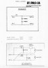
I have a number of EV FM12-2 PA floor monitors (2 way, EVM12L woof and T35 tweet) that sound very different from each other. They are from various years and were acquired at different times. In trying to research these speakers I've been unable to find a schematic for the crossovers so I drew the one below from an example that I have. I haven't taken them ALL apart but the ones I have that work and that I've disassembled appear to be like the drawing. I do have a single uninstalled crossover that has a different "protection circuit" but otherwise appears to have the same parts and construction.

The parts from one example as found, measured with Atlas LCR40 tester:
C1 = 16uF (actually 2 parallel caps, 10uF and 6uF)
L1 = 1.3mH
C2 = 1.5uF
L2 = .44mH
I'm not absolutely sure that these measurements are correct as I don't have much experience with this tester. The inductance figures are indicated as measured at 15KHz. I was led to believe that inductance was relatively independent of frequency. Is that correct? More to the point, does anyone have experience with the Peak Electronic Design Atlas LCR40 and inductor measurement accuracy?
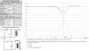
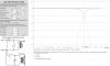
Here's the real problem - these numbers appear to produce a very wrong result when applied to various online 2nd Order crossover simulations. Wrong in that the Electro Voice docs mention a crossover frequency of 5KHz. The parts values above seem to generate a crossover of approximately 2.5KHz and it "looks" very uncharacteristic. See included pics. I understand that the caps may have drifted but I'm not sure how far to expect the inductors to have possibly wandered.

Does anyone have a real EV schematic for these FM12-2 or FM12-2A speakers or the at least the original parts values? Any other guidance?
I hope I haven't committed any unforgivable sins here. Thanks and, Help?
-Tim
I have a number of EV FM12-2 PA floor monitors (2 way, EVM12L woof and T35 tweet) that sound very different from each other. They are from various years and were acquired at different times. In trying to research these speakers I've been unable to find a schematic for the crossovers so I drew the one below from an example that I have. I haven't taken them ALL apart but the ones I have that work and that I've disassembled appear to be like the drawing. I do have a single uninstalled crossover that has a different "protection circuit" but otherwise appears to have the same parts and construction.
The parts from one example as found, measured with Atlas LCR40 tester:
C1 = 16uF (actually 2 parallel caps, 10uF and 6uF)
L1 = 1.3mH
C2 = 1.5uF
L2 = .44mH
I'm not absolutely sure that these measurements are correct as I don't have much experience with this tester. The inductance figures are indicated as measured at 15KHz. I was led to believe that inductance was relatively independent of frequency. Is that correct? More to the point, does anyone have experience with the Peak Electronic Design Atlas LCR40 and inductor measurement accuracy?
Here's the real problem - these numbers appear to produce a very wrong result when applied to various online 2nd Order crossover simulations. Wrong in that the Electro Voice docs mention a crossover frequency of 5KHz. The parts values above seem to generate a crossover of approximately 2.5KHz and it "looks" very uncharacteristic. See included pics. I understand that the caps may have drifted but I'm not sure how far to expect the inductors to have possibly wandered.
Does anyone have a real EV schematic for these FM12-2 or FM12-2A speakers or the at least the original parts values? Any other guidance?
I hope I haven't committed any unforgivable sins here. Thanks and, Help?
-Tim