• The move to the new server is done. There are some software and database maintenance updates in process. This has us passing the hat around to help out. We appreciate any donations. Seriously, even a dollar helps. The payment page may be found here - https://www.audiokarma.org/support.html

Epicure Model 2 Crossover Inductor Question...

mrwasabihead

Fix or restore..fix or restore..fix or restore?
Subscriber
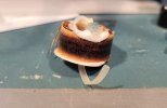
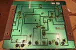
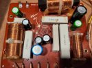
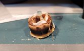
Greetings, this is my first post to the "speaker" forum and it's in regard to a pair of Epicure Model 2 speaker crossovers. I've recapped the two crossovers successfully and one speaker works perfectly and sounds great, the other.....not so much. I swapped out all 4 drivers with the other speaker, as well as check their impedance etc., and the drivers are fine. The crossover board is pretty robust so I pulled all of the newly installed caps just to be sure I didn't install something in the wrong place and it's all correct. The two woofers are responding but maybe at a level slightly lower than I would expect. The main issue is that the mid and the tweeter are all but silent. I've checked all other components on the board, resistors, inductors and solder connections, so I'm thinking that it's the inductor that seems to be the problem. It looks like it's suffered a good deal of heat and the curse of the "happy glue gun guy" but it's the measurements that give me pause. Where the air core inductor sits on the board it reads, "160 UH" I'm assuming that that's 160 micro Henry.
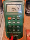
I've got a decent LCR meter and the inductor measures: 4.0uH / 0.17 Ohm. So I'm assuming the inductor is indeed bad and wondering where might I find a replacement. Parts Express seems to have air core inductors but only up to 16uH. As the DCR for their 16uH inductor is "2.66 Ohm" I'm assuming that this 160uH inductor should be a lot higher than 0.17 Ohms.
Any input and assistance would be appreciated.
Mark
 

Attachments

  • 1.jpg
    1.jpg
    158.1 KB · Views: 13
  • 2.jpg
    2.jpg
    160.6 KB · Views: 14
  • 3.jpg
    3.jpg
    88.5 KB · Views: 14
  • 4.jpg
    4.jpg
    144.6 KB · Views: 17
  • 7.jpg
    7.jpg
    414.3 KB · Views: 18
  • 8.jpg
    8.jpg
    123.4 KB · Views: 17
  • 9.jpg
    9.jpg
    125.9 KB · Views: 11
  • 10.jpg
    10.jpg
    125.3 KB · Views: 9
  • 11.jpg
    11.jpg
    109.5 KB · Views: 13
Register to hide this ad
Thanks for the responses and suggestions. I pulled the other crossover, pulled the air core inductor leads and measured it - it measured 161uF @ .58 Ohm.
So it looks like the one I was worried about is indeed toast. Having followed the link "swechsler' provided I found that there are only two that come close to the measurements I got from the working coil - those being:
The differences between the two that I notice are that the wire gauge of the original coil seems to be AWG 26 (0.02in / 0.7mm) and these are 20 gauge, and the DCR of these is almost half of the measured value from the working coil. I've also used several inductance calculators I've found online, for self educational purposes, and given the results of the calculation shown below they match up pretty well - except for the fact that this calculation was done with 24 gauge wire and my coil wire is most likely 26 gauge. With 26 gauge wire used in the calculation I end up with a 0.76 Ohm inductor. It seems like the smaller diameter the wire the higher resistance per foot...maybe. Or, assuming that my coil is indeed 26 gauge, is it possible that the original coil might have been of a higher resistance originally than the .58 Ohm I'm measuring from the good inductor currently?
 

Attachments

  • Epicure inductor calc_2.JPG
    Epicure inductor calc_2.JPG
    68.4 KB · Views: 5
Last edited:
It's quite possible they used a thinner gauge wire, and yes, that will increase the resistance slightly. But the difference will be inaudible. If it concerns you, replace both.
 
I'll certainly replace both inductors when I find a suitable replacement but does the halving of the resistance I'm finding between the original (0.5 Ohm) and the .23 Ohms of the only close replacement I'm currently finding going to matter either electrically or audibly? Also the only one I've found available is almost twice the diameter, 35mm as opposed to 21mm, and I'm wondering if there's such a thing as too big - even if it will "fit" in the space available. Are there possible interrfearence issues if it's physically larger than the last one, i.e. proximity issues with other components etc.? From the two in here it looks like heat might be a factor.
 
Last edited:
Inductors in a crossover should either be installed several inches apart (I don't remember the exact distance) or in a different plane (i.e. along the x-axis, y-axis, or z-axis, if you consider the axis to be the cylinder that the coil is wound on) from adjacent inductors. So if you install this one flat against the board, it should be fine. The difference in resistance is so small as to be inconsequential. And consumer speaker crossovers don't experience significant heat unless the speakers they are part of are being abused. In almost all cases this will be audible before it starts causing damage. I wouldn't worry about it.
 
The inductor that I just ordered from PE (Dayton-Audio-AC20-15-0.15mH-20-AWG-Air-Core-Inductor-Coil-257-022) probably won't fit in the spot that old one came out of. It's 38mm in dia. compared to the 21mm dia of the original. In the pic below you can see the outer ring where the original inductor was installed is 25mm in dia. And the original was only 21mm. So it's not going to fit in the same way. Installing it in on it's edge would put it on the same axis as the other inductors so I've been wondering if a stand-off of some kind to raise it up over the surrounding caps and resistors might be the answer, or possibly installing it on the back and using stand-offs to raise the circuit board - but if neither of those options are viable I'll have to continue looking for a different inductor. There doesn't seem to be much available out there.
 

Attachments

  • 25mm dia.jpg
    25mm dia.jpg
    124.3 KB · Views: 7
From how shiny the caps look, I assume you have already recapped that board using electrolytic caps. If you have not yet recapped and plan on using film caps, the size difference in caps will make positioning the inductor seem easy.

It looks like the crossover board is mounted inside the cabinet. You can attach the inductor to the cabinet beside the crossover board. The inductor does not have to mounted on the PCB. You can use hookup wire to extend the leads from the inductor to the crossover board. I would use zip cord for the hookup wire.
 
The inductor that I just ordered from PE (Dayton-Audio-AC20-15-0.15mH-20-AWG-Air-Core-Inductor-Coil-257-022) probably won't fit in the spot that old one came out of. It's 38mm in dia. compared to the 21mm dia of the original. In the pic below you can see the outer ring where the original inductor was installed is 25mm in dia. And the original was only 21mm. So it's not going to fit in the same way. Installing it in on it's edge would put it on the same axis as the other inductors so I've been wondering if a stand-off of some kind to raise it up over the surrounding caps and resistors might be the answer, or possibly installing it on the back and using stand-offs to raise the circuit board - but if neither of those options are viable I'll have to continue looking for a different inductor. There doesn't seem to be much available out there.
Looks like a fun project! While you have everything torn apart, I would take some alcohol and clean all the flux off of the copper side of your crossover boards. It will tidy it up nicely and save you any corrosion problems down the line:)
 
I have actually already recapped the boards and the nearest caps to where original inductor went are both 10uF so I suppose I could have gone film for those. Good reminder, thanks! Mounting the new inductor off the board and running leads sounds like a good solution, I hadn't thought of that. I'll give it a try, thanks again!
 
The new coils from Parts Express arrived today and I'd take come pics but my phone camera is suffering from a foggy lens due to humidity!
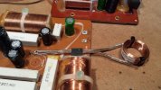
I used 16GA stranded speaker wire for the leads to the new coils and decided to run this wire over the board instead of underneath. It looks like there was 2 1/8" in. separation from on center of the other three inductors originally so I used the same separation for the off-board positioning.
The results are excellent. The mid and tweeter that were previously not working are back on line and these speakers sound surprisingly nice.
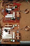
At the moment I'm using a rather low powered NAD shop receiver to listen to them but I know they'll sound better with a higher powered "warmer" sound source. So all in all I'm happy, and appreciate all the input given in repairing these crossovers. I'm doing several coats of Boiled Linseed oil on the real wood cherry veneer of the cabinets and I'll throw up some final pics once I get my camera situation sorted out but for now here are some pics of the crossover repair.
 

Attachments

  • 2.jpg
    2.jpg
    91.5 KB · Views: 10
  • 3.jpg
    3.jpg
    272.9 KB · Views: 10
Yeah, this series from EPI isn't all that well known, but I used to have a pair of Model 3s in the same series, and I thought they were quite good. They're not really traditional EPIs (by the time these speakers came out, that ship had sailed), but that's not necessarily bad. They were obviously going for a higher end vibe, with wood veneer on all surfaces but the bottom, hidden connections, real binding posts (which was something of a rarity at the time), and heavy duty internal wiring. They even originally shipped with removeable spikes.
 
Back
Top Bottom