ChrisPDX
New Member
I recently acquired a used Adcom GFA-2535, which is two GFA-535 amps (MKII version, if I understand correctly) in one unit. These amps can be run independently in “stereo” mode or in “bridged” mode. This unit does not have input-level control dials.
I wanted to check the amps' DC offsets before hooking them up, in order to make sure they were performing well and would not damage my speakers. While researching how to do this, I found contradictory advice on the state in which to test the power amps’ speaker outputs for DC offset voltage, including this informative FAQ from Adcom specialist “Hoppe’s Brain”:
So I tested the Left and Right channels on both amps (A & B, in “Stereo” mode, warmed-up) in three states:
........... NO SIGNAL.... 1KHz TONE . INPUT SHORTED
...AMP A -------------------------------------------
.....RIGHT .... 33 mV ...... 104 mV ........ 102 mV
.....LEFT .... -18 mV ....... 80 mV ......... 79 mV
...AMP B -------------------------------------------
.....RIGHT ..... 9 mV ...... 101 mV ......... 99 mV
.....LEFT ...... 3 mV ....... 93 mV ......... 90 mV
Any advice on how to interpret these results would be much appreciated !
Based on the measurements with no signal input, Amp B looks pretty good and Amp A looks marginal, but all of the other test results seem quite high (again per Hoppe's Brain above: the MKII "should be very close to 0V, whether you have the inputs shorted or not. Normal range is less than 5mV"). If Amp B is good to go, I would be happy to just use that one alone and not take this unit in for servicing.
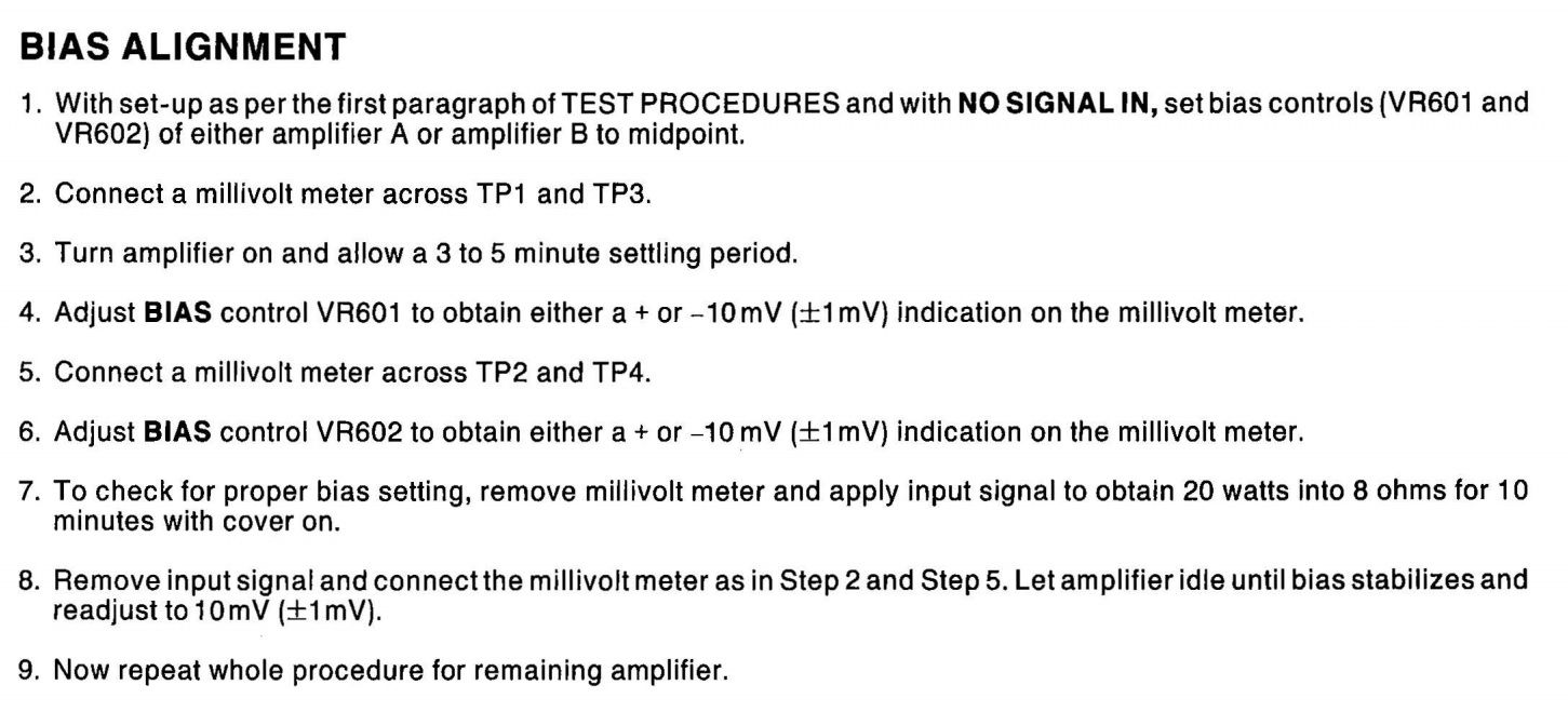
( For reference, the Adcom GFA-2535 Service Manual is here. )
Secondary question: Assuming I proceed to only use Amp B, is there a non-permanent way to disconnect Amp A in order to not waste energy and to remove a potential source of electrical noise?
Thank you for your assistance! This website is a great resource, and I really appreciate the time and effort so many users devote to helping others learn.
( I hope no one minds that I took the liberty of tagging users who seem to have relevant experience: @Wolverine @Mayank @northpaw @Skywatcher @SaturationPt @Frank Sol @AdamAnt316 @SteveJewels )
I wanted to check the amps' DC offsets before hooking them up, in order to make sure they were performing well and would not damage my speakers. While researching how to do this, I found contradictory advice on the state in which to test the power amps’ speaker outputs for DC offset voltage, including this informative FAQ from Adcom specialist “Hoppe’s Brain”:
How much DC offset is normal?
DC offset should be measured with the input shorted. (You can make a shorting plug from an old patch cord, just cut the wire about 1″ long and solder the wires together.)
- GFA-535, 545, 555 MKI. Normal from the factory is about 40mV. With a pair of carefully matched input transistors, such as the ones I sell, you can expect less than 20mV. If you see much more than 50mV the amplifier should be checked out.
- GFA-535, 545, 555 MKII, GFA-565, GFA-585
These amps contain DC servo circuits, and so DC offset should be very close to 0V, whether you have the inputs shorted or not. Normal range is less than 5mV, and it may slowly drift around a bit.
So I tested the Left and Right channels on both amps (A & B, in “Stereo” mode, warmed-up) in three states:
- No signal
- 1000 HZ tone (from iPhone signal generator app at 75% volume)
- RCA input shorted
........... NO SIGNAL.... 1KHz TONE . INPUT SHORTED
...AMP A -------------------------------------------
.....RIGHT .... 33 mV ...... 104 mV ........ 102 mV
.....LEFT .... -18 mV ....... 80 mV ......... 79 mV
...AMP B -------------------------------------------
.....RIGHT ..... 9 mV ...... 101 mV ......... 99 mV
.....LEFT ...... 3 mV ....... 93 mV ......... 90 mV
Any advice on how to interpret these results would be much appreciated !
Based on the measurements with no signal input, Amp B looks pretty good and Amp A looks marginal, but all of the other test results seem quite high (again per Hoppe's Brain above: the MKII "should be very close to 0V, whether you have the inputs shorted or not. Normal range is less than 5mV"). If Amp B is good to go, I would be happy to just use that one alone and not take this unit in for servicing.
( For reference, the Adcom GFA-2535 Service Manual is here. )
Secondary question: Assuming I proceed to only use Amp B, is there a non-permanent way to disconnect Amp A in order to not waste energy and to remove a potential source of electrical noise?
Thank you for your assistance! This website is a great resource, and I really appreciate the time and effort so many users devote to helping others learn.
( I hope no one minds that I took the liberty of tagging users who seem to have relevant experience: @Wolverine @Mayank @northpaw @Skywatcher @SaturationPt @Frank Sol @AdamAnt316 @SteveJewels )
Last edited: