• The move to the new server is done. There are some software and database maintenance updates in process. This has us passing the hat around to help out. We appreciate any donations. Seriously, even a dollar helps. The payment page may be found here - https://www.audiokarma.org/support.html

external dc powered motherboard with a 4-pin mini din socket

dilettante

Well-Known Member
I tried researching this question myself and I hope someone knows the answer. I'm doing my own pc music server and am perplexed. Thanks for reading on.

I have a mini-ITX mobo to go in an appropriate streacom case with a low TDP cpu. In every other respect the mobo has all the things I want with no things I don't want.

But the mobo requires an external dc power source to the rear I/O panel and it's not a barrel socket but rather a 4-pin mini din socket.

Now, I have some limited experience concerning 4-wire dc power *sources." In the cases I know about, there are two pairs of hot and neutral wires. One pair is actually supplying the dc power to the power-eating device; but the other pair is monitoring power draw at the power-eating device to quickly compensate for fluctuations in the power consumption. I have four Acopian LPSs that have 4 power terminals, one pair for supply and one pair for this monitoring.

In past situations I found that when my power supply has this feature, I can still run a quad power cable from the power supply's four terminals (remember, 2 pairs of hot and neutral) to a 2-conductor plug like a barrel connector without that causing any problem. But this has always been in cases where the power-eating device only seems to "want" a two-conductor feed (as with a barrel socket on a motherboard or laptop).

In my current situation, though, the power-eating device actually has a 4-condutor socket (for a 4-pin mini din plug). I don't know what to make of this and is frequently the case, the website of the mobo maker is no help at all. I don't want to fry the mobo. Suppose I have a linear dc power supply with only two outputs (rather than the four on those Acopians I mentioned earlier) and I just connect the one hot conductor to the mobo's two hot inputs (and the one neutral conductor to the mobo's two neutral inputs). Does anyone know whether this is a huge mistake that will convert my mobo into an interesting paperweight?

Thanks for your thoughts!
 
Register to hide this ad
It seems possible that the two pairs of dc power pins are a reliability thing. The mobo is described as an "industrial" mobo in some places. It might be that such mobos typically have a pair of independent power inputs for reliability. Many industrial servers have a pair of independent power supplies in case one fails (I have a Dell server with this feature). Does that sound plausible? If so, would it matter whether I fed both pairs of dc inputs from a single dc power source (except for reliability)?

Thanks for your thoughts.
 
Did you already have a look at the PCB traces below that 4-pin connector on that mainboard? Maybe they are simply using two pins in parallel to reduce the current per pin (and per wire in the power supply cable)...

Greetings from Munich!

Manfred / lini
 
It seems possible that the two pairs of dc power pins are a reliability thing.

ITX boards normally have a standard connector. I think you need to find some technical data on the device you are using (you haven't identified it here).

Multiple pins might also support multiple voltages. As Manfred suggests, you might be able to trace or buzz out the connections.
 
Thanks folks. I think Manfred's suggestion may have been a good one, but I'd love other opinions.

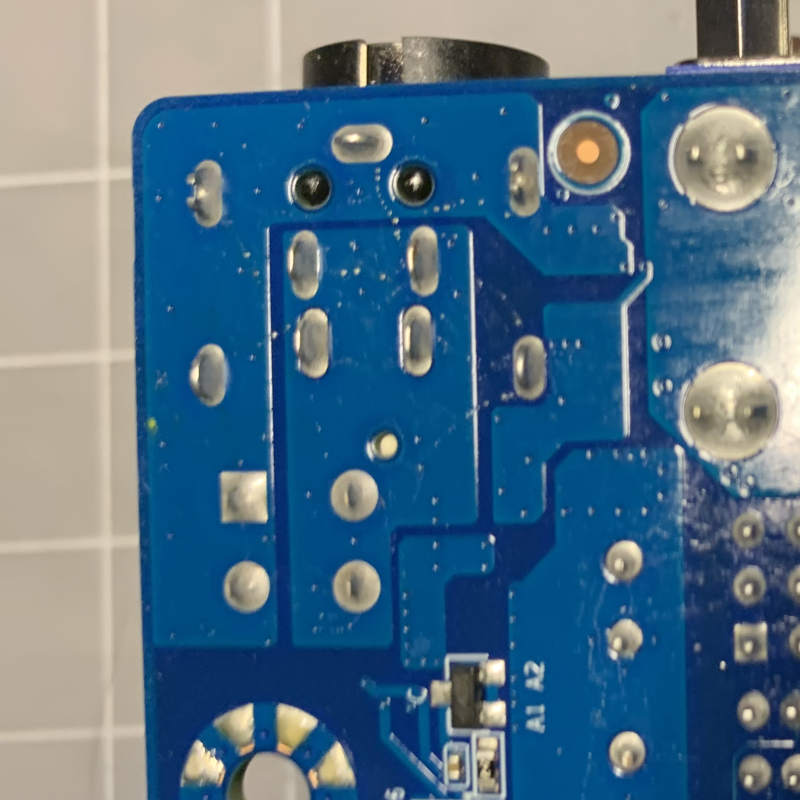
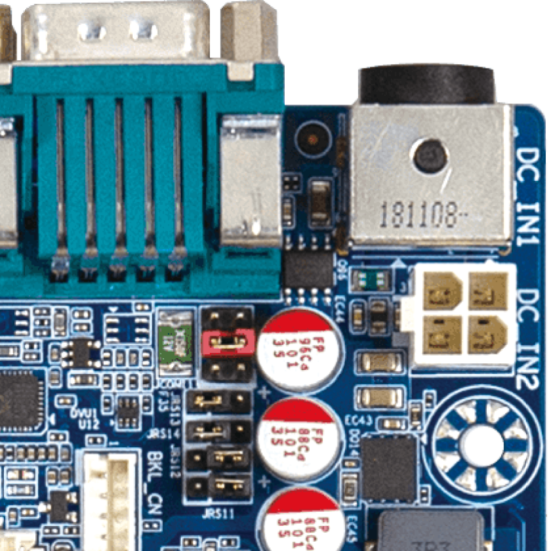
I embedded bottom and top images of the power corner of the mobo (the former has the traces I believe). You can see the round rear I/O power socket sticking out at the top of both images. It looks to me like it is attached to the mobo with eight pins: A larger rectangle of four pins appears to be largely connected to one trace, while a smaller square of four pins (within the larger rectangle) appears to be wholly connected to a different trace.

I see a 4-pin interior molex socket just below the rear I/O connector, supporting (I guess) an interior psu if one likes. It connects two of its pins to the same trace as the larger rectangle of four pins (of the rear I/O socket), and its other two pins to the same trace as the smaller square of four pins (of the rear I/O socket).

I'm getting a sense that Manfred's idea that "Maybe they are simply using two pins in parallel to reduce the current per pin (and per wire in the power supply cable)" makes sense, given the trace sharing between the interior 4-pin molex socket and the rear I/O socket.

I do appreciate your input.

The mobo is here: https://www.gigaipc.com/index.php?action=products3&cid=1&tid=2&pid=62
 
Last edited:
Yes, thanks for pointing out the manual. I had read it already, and didn't regard the information given as a "full" description as you did. Interpretation depends on assumptions made prior to reading. But thanks.
 
dilletante: The outer 4 pins simply connect the metal case of the connector with the ground plane of board, so these basically serve to hold it in place and as shield ground. And the fifth pin between the upper two is another shield ground for the ring contact.

Next down follow the upper, slightly more widely spaced pin pair, both pins of which are connected to the positive power input trace in parallel (as are the two inner pins of the ATX-style 4-pin connector (= DC_IN2).

And if you look closely at your picture of the underside, you can see, that the lower, slightly less widely spaced pin pair actually isn't connected to the positive power input trace - which is a bit hard to spot, though. So one can assume, that these two pins are connected to another ground plane trace on another layer of the board - most likely to the same trace as the fourth outer pin (i.e., the lower right one, as seen from the underside), I'd guess.

So from visual inspection one can definitely say, that the two positive power input pins are simply used in parallel, as already suspectted - and that the two ground pins wouldn't be used in parallel as well, would seem highly unlikely.

So if you have a power supply with barrel plug, you could either make yourself an adaptor (or buy one, if available) or alternatively remove the barrel plug and replace it with such a 4-pin plug, on which I'd also suggested to use the two pin pairs in parallel too reduce the current per pin (as well as the overall contact resistance).

Greetings from Munich!

Manfred / lini
 
This sounds mostly like what I thought--though I didn't know what to make of the pin that didn't seem to connect to any visible trace. The presence of "layers" in the pcb is new to me. I am, after all, a dilettante (even to the point of misspelling it--need to fix that).

Your suggestion "So if you have a power supply with barrel plug, you could... remove the barrel plug and replace it with such a 4-pin plug, on which I'd also suggested to use the two pin pairs in parallel too reduce the current per pin (as well as the overall contact resistance)" is what I intended to do before these doubts crossed my mind, and I have what I need for that including quad power cable to reduce the current per wire and pin, so I think I will go ahead with that. Thanks a lot for your attention to my doubts and an interpretation that makes sense--oh and I certainly won't blame you if I end up frying the mobo!
 
It seems possible that the two pairs of dc power pins are a reliability thing. The mobo is described as an "industrial" mobo in some places. It might be that such mobos typically have a pair of independent power inputs for reliability. Many industrial servers have a pair of independent power supplies in case one fails (I have a Dell server with this feature). Does that sound plausible? If so, would it matter whether I fed both pairs of dc inputs from a single dc power source (except for reliability)?

Thanks for your thoughts.

I agree with this. Industrial mobos and PC machines, pay special attention to redundant power and even cooling. Why? Simple. They run things which depend on industrial strength reliability and stabiltiy doing critical workloads which must not fail easily. Major priority over consumer grade hardware. Agree with your logic and thinking here. More rugged, resilent, and tolerant of faults which cause lesser to fail.
 
(...) The presence of "layers" in the pcb is new to me. (...)

Well, maybe you've just never seen it mentioned (*) - but in fact computer mainboards already have required more than one or two layers for quite a long time, simply due to all those multi-contact chips (and also pretty dense multi-pin connectors like for example RAM sockets...) requiring far too many traces (and not rarely also reasonably short ones to ensure proper signals timings...) for single- or dual-layer signal routing. Hence manufacturers came up with additional layers, sandwiched in between, which the consumer can't really see, but could conclude to their presence, if a component leg/pin has to be connected to some trace for proper function, albeit not being connected to a visible trace. Not sure, whether that also goes for that lower right outer pin of the connector shell in your bottom-side pic, though - as three ground contacts would already seem good enough for that.

Greetings from Munich!

Manfred / lini

*) Nowadays multi-layer boards would already seem so commonplace, that manufacturers might not feel inclined to mention the actual number of layers anymore, unless a certain board would set a new record in its category.
 
Thank you Manfred. I lived in Wiesloch, a tiny town south of Heidelberg, for a year when I was young enough to attend the public schools and pick up the language on the fly. But my Deutsch has faded away and is now sehr schlecht. My dad was doing in-residence research at the Nietzsche archive then located in Heidelberg. Not as far from Munich as one can be in Germany.

I powered up the motherboard and it failed the POST, issuing beep codes suggesting a problem with the RAM (but I don't know this since the manual is lousy--doesn't have a BIOS section or even state the BIOS maker and forget about a POST beep code section). On the bright side, there were no electrical smells, sparks, or fireworks. I'm trying to track down the issue using the usual home remedies. The manual also fails to fully specify the characteristics of compatible RAM. I have sent some inquiries to their tech support.

I used to build all our home computers until about 20 years ago, and a lot has changed since then. I have never fried a motherboard or any other component (in spite of several edgy mods over the years), but of course there's a first time for everything. :cool:

Greetings from the Blue Ridge!
 
Last edited:
Because my issues have moved deep into the weeds of POST beep codes (failure to even get to the place where I can view and edit BIOS settings), I think we're done here. My thanks again to the three of you. I may open a new thread reporting on the emerging issue to see if anyone has wisdom on it.
 
Suppose I have a linear dc power supply with only two outputs

One last thought: does the linear PSU have enough grunt to power the motherboard? Assuming the quoted TDP of 65W is also the actual power requirement (not unreasonable), that's quite a lot for a linear PSU. I'd try a standard 19V 85W SMPS first. I have a bunch of Lenovo 19V 65W and 85W laptop supplies I salvaged from the skip at work. Those BIOS beeps might be trying to tell you it's suffering power-up brownouts.
 
You're right. Right now, the only 12v power supply I have with the correct 4 pin mini-din connector (with the correct polarities) is a 60W switching supply. I estimate the power needs of the mobo with all my stuff on it to be about 73W and the processor has a TDP of 35W. The linear supply I have is 120W* to cover that with headroom BUT I don't have the correct cable to use it yet: A company in MA is making that cable for me (my old hands don't work for that kind of soldering.) But you're definitely right and, In sha'Allah, I'll know about that in a week or so.

*That's high for a top-shelf linear, but this psu is middle-shelf.
 
Good luck - hope you can finally make it work. And I'd agree, that the manual for the board wouldn't seem all too detailed and helpful.

I lived in Wiesloch, a tiny town south of Heidelberg, (...)

Never been there myself - but of course I'm aware of it, as it's often named together with its neighbour town Walldorf, where SAP is located.

Greetings from Munich!

Manfred / lini
 
Here's a denouement on this thread.

I never did get this motherboard to boot. I had a suitable power cable made so that a more-than-adequate power supply could power it and that did not allow the motherboard to boot. I got a second pair of RAM--no luck. I corresponded with the maker's tech support and, after a bit of (very cordial) back-and-forth with them, I got an RMA authorization and have returned it. I purchased a different motherboard in the meantime and am near to giving it a try.

I have this to say about the experience. Most mini-ITX mobos with a rear I/O connection for external DC power have a barrel jack of some measurement. The 4-pin mini-din is unusual; and the pin polarity of the mobo I originally bought is even more unusual--very few external AC-to-DC psus have that polarity. Be more vigilant than I was about these matters.

Again, my thanks to everyone who helped me out with this.
 
Back
Top Bottom