matjo
Member
Dear highly regarded Sansui-specialists.
First of all, I hope everybody is healthy and safe in this strange, strange corona-time.
After restoring a 555a with the help of Leestereo, Stereofun, Slimcity and The Fuxtor, I decided this time to do another project, a AU-101. Still not a professional electro-technical Engineer (not even on amateur level I suppose), but learning every time more and more (where this Forum is a huge base of knowledge).
After the recap, I am confronted with a problem: The right channel of the Phono-stage is not working. AUX is doing fine, so I guess it would be a problem on the F-1303 board, at the Phono-preamp.
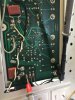
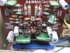
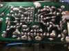
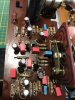
I had no idea where to start. I double checked the Transistor-wiring (KSC1845FTA), I desoldered and desoldered every component. Checked the solder joints. Checked for broken leads (due to the amount of soldering I ruined a few places, but was able to fix them, see pictures attached).
Even bought another AU-101 to compare. started to measure the DC-voltage on the F-1303, starting on the other side of the board. And there my curiosity started: The results were very, very different, also compared to what is stated on the schematic in the user manual.
on original AU-101: voltage after R002: 21,91V (schematic states 22,5V) - I have 30V !
on original AU-101: voltage after R615 & R616: 10V (like on schematic) - I have on R616 29,9V, on R615 16V !
on original AU-101:voltage after R609 & R610: 1,77V - I have on R609 2V and on R610 8,6V !
If I test the resistors, they seems to be fine, simular to the values in the schematic.
I must say that I do not own a super-reliable device like a Fluke; I am stuck with a much cheaper multi-meter, an even cheaper capacitor/transistor ESR meter and a very old Hameg 20 Mhz Oscilloscope (HM-203-5).
Measured all the values of the replaced components; they where all good.
WHAT AM I NOT SEEING? Am I looking at the right place???
I have attached some pictures to be more clear; really hope somebody can tell me where I am making a mistake.....


I have changed the following components:
C601-602 Radial Leaded Aluminium Electrolytic Capacitors - Radial Leaded 1uF 50V 20% Audio SILMIC II
TR601-604 & TR701-702 KSC 1845FTA Bipolar Transistors
C001 Snap In Aluminium Electrolytic Capacitors - Snap In 4700uF 63 Volts 20% Tol.
C605-606-609-610 Radial Leaded Aluminium Electrolytic Capacitors - Radial Leaded 10uF 25V 20% Audio SILMIC II
C003-004 Radial Leaded Aluminium Electrolytic Capacitors - Radial Leaded 50volts 470uF 16x35.5
C603-604-607-608 Film Capacitors 68pF 1000 Volts 5%
C611-612 Radial Leaded Aluminium Electrolytic Capacitors - Radial Leaded 4.7uF 25V 20% Audio SILMIC II
C613-614 Film Capacitors 100V 0.012uF 5% LS=5mm
C615-616 Film Capacitors 4700 pF 63 VDC 2.5%
C617 Film Capacitors 220 pF 100 VDC 2.5%
C618 Film Capacitors 250V 0.033uF 5% LS=5mm
C701-702 Film Capacitors 330 pF 100 VDC 2.5%
C703-704-715-716 Film Capacitors .022uF 63 Volts 5%
C703-704 Film Capacitors 0.022 uF 100 VDC 5%
C713-714 Film Capacitors 2200 pF 63 VDC 2.5%
C713-714 Film Capacitors 2200pF 63 Volts 10%
C717-718 Film Capacitors 22000pF 100V 1% Orange Drop
C719-720 Film Capacitors 630VDC 0.22uF 10% MPP L/S=7.5mm
First of all, I hope everybody is healthy and safe in this strange, strange corona-time.
After restoring a 555a with the help of Leestereo, Stereofun, Slimcity and The Fuxtor, I decided this time to do another project, a AU-101. Still not a professional electro-technical Engineer (not even on amateur level I suppose), but learning every time more and more (where this Forum is a huge base of knowledge).
After the recap, I am confronted with a problem: The right channel of the Phono-stage is not working. AUX is doing fine, so I guess it would be a problem on the F-1303 board, at the Phono-preamp.
I had no idea where to start. I double checked the Transistor-wiring (KSC1845FTA), I desoldered and desoldered every component. Checked the solder joints. Checked for broken leads (due to the amount of soldering I ruined a few places, but was able to fix them, see pictures attached).
Even bought another AU-101 to compare. started to measure the DC-voltage on the F-1303, starting on the other side of the board. And there my curiosity started: The results were very, very different, also compared to what is stated on the schematic in the user manual.
on original AU-101: voltage after R002: 21,91V (schematic states 22,5V) - I have 30V !
on original AU-101: voltage after R615 & R616: 10V (like on schematic) - I have on R616 29,9V, on R615 16V !
on original AU-101:voltage after R609 & R610: 1,77V - I have on R609 2V and on R610 8,6V !
If I test the resistors, they seems to be fine, simular to the values in the schematic.
I must say that I do not own a super-reliable device like a Fluke; I am stuck with a much cheaper multi-meter, an even cheaper capacitor/transistor ESR meter and a very old Hameg 20 Mhz Oscilloscope (HM-203-5).
Measured all the values of the replaced components; they where all good.
WHAT AM I NOT SEEING? Am I looking at the right place???
I have attached some pictures to be more clear; really hope somebody can tell me where I am making a mistake.....
I have changed the following components:
C601-602 Radial Leaded Aluminium Electrolytic Capacitors - Radial Leaded 1uF 50V 20% Audio SILMIC II
TR601-604 & TR701-702 KSC 1845FTA Bipolar Transistors
C001 Snap In Aluminium Electrolytic Capacitors - Snap In 4700uF 63 Volts 20% Tol.
C605-606-609-610 Radial Leaded Aluminium Electrolytic Capacitors - Radial Leaded 10uF 25V 20% Audio SILMIC II
C003-004 Radial Leaded Aluminium Electrolytic Capacitors - Radial Leaded 50volts 470uF 16x35.5
C603-604-607-608 Film Capacitors 68pF 1000 Volts 5%
C611-612 Radial Leaded Aluminium Electrolytic Capacitors - Radial Leaded 4.7uF 25V 20% Audio SILMIC II
C613-614 Film Capacitors 100V 0.012uF 5% LS=5mm
C615-616 Film Capacitors 4700 pF 63 VDC 2.5%
C617 Film Capacitors 220 pF 100 VDC 2.5%
C618 Film Capacitors 250V 0.033uF 5% LS=5mm
C701-702 Film Capacitors 330 pF 100 VDC 2.5%
C703-704-715-716 Film Capacitors .022uF 63 Volts 5%
C703-704 Film Capacitors 0.022 uF 100 VDC 5%
C713-714 Film Capacitors 2200 pF 63 VDC 2.5%
C713-714 Film Capacitors 2200pF 63 Volts 10%
C717-718 Film Capacitors 22000pF 100V 1% Orange Drop
C719-720 Film Capacitors 630VDC 0.22uF 10% MPP L/S=7.5mm