• The move to the new server is done. There are some software and database maintenance updates in process. This has us passing the hat around to help out. We appreciate any donations. Seriously, even a dollar helps. The payment page may be found here - https://www.audiokarma.org/support.html

Failed LTSpice Simulation of HK Citation II

LinuxGuru

Well-Known Member
Hi,

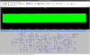
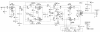
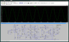
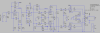
I have some difficulty with LTSpice simulation of HK Citation II. The only difference from the original is an output CFB transformer (real unit with real DCR of windings). Simulated amp oscillates even at low input signal level. Polarity of secondary connection (to GND / global feedback) is correct, reversing it causes huge spikes. Suppressor grid of 12BY7 pentode is connected to cathode in schematic, yet LTSpice models made as tetrodes with that connection already in place. 12BY7 models are by Ayumi (used), and another by Steve/Stepnie Bench (unused). Tried second, sim doesn't work either. All files in attachment.

Made similar simulations in the past, they were surprisingly close to real units when they were built and measured, even THD values.

I can't understand purpose of 4uF C7 (on original manufacturer's schematic), which is connected between grid and screen ("-" of that cap IMHO should go to the ground), but don't think its a bug in drawing.

Thanks in advance for any help.
 

Attachments

  • Screenshot at 2022-11-15 17-28-37.png
    Screenshot at 2022-11-15 17-28-37.png
    139.7 KB · Views: 23
  • Screenshot at 2022-11-15 17-28-09.png
    Screenshot at 2022-11-15 17-28-09.png
    167.7 KB · Views: 23
  • cit2_schematic.png
    cit2_schematic.png
    171.9 KB · Views: 25
  • Amp_Cit2.zip
    Amp_Cit2.zip
    657.8 KB · Views: 5
Register to hide this ad
It goes from screen to cathode. Not unusual and should be just fine connected that way. Looks like you show it that way in your spice schematic. I would break the feedback loop and do a gain phase analysis.
 
Actually, there are many feedback loops in that amp, but it's likely the global one around the transformer that needs attention..
 
Looks like your LFB1 and LFB2 are not drawn correctly. It's hard to make out the details on the original schematic due to poor resolution.
 
Your spice drawing of the feedback around U7 and U8, through the 20 pF capacitors and 1 Meg resistors is also incorrect. You need to be a bit more careful on schematic capture.

Good luck and let us know how it works when corrections are complete.
 
C7 runs from screen to cathode, which is correct. It keeps the cathode and the screen at the same AC potential. Without it you get some extra negative feedback as the voltages move relative to one another with signal.
 
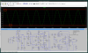
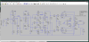
Actually there were 2 bugs in my LTSpice schematic. I corrected them and now it works. What is that strange shift of output signal symmetry, marked with red lines? Warm up of the amplifier?

PS. Steve/Stephie Bench 12BY7 LTSpice model (marked with "_sb" suffix) seem to be buggy.
 

Attachments

  • Amp_Cit2.zip
    Amp_Cit2.zip
    852.3 KB · Views: 2
  • Screenshot at 2022-11-16 10-46-17.png
    Screenshot at 2022-11-16 10-46-17.png
    211.3 KB · Views: 9
  • Screenshot at 2022-11-16 10-46-55.png
    Screenshot at 2022-11-16 10-46-55.png
    204 KB · Views: 10
1 would be a perfect transformer. So < 1 is closer to reality.
I have no answer but maybe someone does.
 
As others have said it’s correct to connect C7 to the cathode if you want the screen to be decoupled relative to the cathode.

Some additional commentary. All voltages in the tube are relative to the cathode, so connecting that cap to ground would decouple the screen to ground, and therefore not to the cathode, which would cause the screen to see an AC signal relative to the cathode, which would cause the gain of the stage to be reduced. (Applies a bit of negative feedback).
 
What is that strange shift of output signal symmetry, marked with red lines?
Likely the result of one or more capacitors charging. It should go away if you set the plot to take data after the circuit has run for one or two seconds.

Jack
 
Last edited:
Original schematics have some oddity (if its not a print bug). Please note grid of the upper U1 KT88 is being connected not to the anode of the phase splitter U7, but to the voltage divider / junction of R11/R13. I checked 2 different release/printouts of Citation II schematics, they all have this connection in this way. In order to balance output signal I made adjustment of 5K potentiometer to ratio 0.95. In turn, this have created considerable asymmetry of anode voltage for 2 tubes of the phase splitter (267V and 320V respectively).

Is this a deliberate way (made by designers of this amp) to increase 2nd order harmonics over 3rd?

Complete set of files attached as always.
 

Attachments

  • Screenshot at 2022-11-21 17-25-06.png
    Screenshot at 2022-11-21 17-25-06.png
    151.8 KB · Views: 9
  • Screenshot at 2022-11-21 17-25-24.png
    Screenshot at 2022-11-21 17-25-24.png
    176.1 KB · Views: 6
  • Amp_Cit2.zip
    Amp_Cit2.zip
    860.1 KB · Views: 2
I'm sure that behavior is not correct. The upper tube of the LTP exhibits more gain than the lower tube because it's driven from the grid, not the cathode. Most LTP designs remedy this imbalance through use of a smaller anode resistor on the input tube. HK chose instead to "tap down" on the anode resistance. Either method should in fact produce a more balanced output and allow setting the AC balance pot more nearly in the center of its travel. That should in turn produce nearly equal anode voltages at the splitter tubes.

I don't usually SPICE complete amplifiers in this way, primarily because I usually assume it won't be possible to accurately assess all the transformer characteristics. That's just me though, and it's not unusual to see amplifiers modelled like you've done here. In any event, my technique for troubleshooting difficult sims generally involves tearing them apart and confirming operation stage by stage. That's probably not justified in this case, but my first suggestion would be to remove the nested loops LFB1 and LFB2, just to see if balance improves. You might also want to remove the 1M/20pF networks temporarily.

My suggestions here need the caveat that I have no hands-on bench experience with the Citation II. I also haven't studied this circuit at the detailed level it probably deserves. I'm just trying to lay out a few general guidelines as to how I approach this sort of problem.

Jack
 
I "normalized" circuit in LTSpice, equal plate load resistors and no potentiometer. Signal is symmetric. So this asymmetry was intention by design.
 
I'm not sure what you mean by normalizing the circuit. However, the AC output of a long tail pair with equal value anode resistors is not balanced. When triodes are used, the anode resistor at the input tube must be reduced in order to balance the two outputs. This typically results in only a small difference in anode voltage between the two tubes.

Jack
 
Where is the AC balance pot "set" to in the sim? Stock its an 8.2k resistor in series with a 5k pot on one side vs a 12k on the other. If the pot value is adjusted so it's set point is 3.8k it should give you a symmetrical output. If its being registered as a 5k resistor you've got 13.2k vs 12k so it will give more output on the top triode.

in reality you set that pot to wherever it has to be in order to make up for component tolerances and imperfect tubes. Also possibly it wants a slightly unbalanced grid drive to compensate for slightly asymmetrical windings in the transformer. Have to set that with an IMD analyzer if you have one, or just scope from grid to grid, sum the inputs and tweak the balance for a null.
 
Where is the AC balance pot "set" to in the sim? Stock its an 8.2k resistor in series with a 5k pot on one side vs a 12k on the other. If the pot value is adjusted so it's set point is 3.8k it should give you a symmetrical output. .

It will not, look how top power tube U1 connected to voltage divider, not straight to the anode of phase splitter.
 
I made a sym of THD analysis, and my assumption of artificial asymmetry in phase splitter was correct. Look at the files attached, voltages at phase splitter anodes, and THD harmonics (1.5V input, 60W output). 2nd order harmonic becomes predominant thanks to asymmetry.
 

Attachments

  • Screenshot at 2022-11-22 11-36-58.png
    Screenshot at 2022-11-22 11-36-58.png
    180.7 KB · Views: 2
  • Screenshot at 2022-11-22 11-40-00.png
    Screenshot at 2022-11-22 11-40-00.png
    208.6 KB · Views: 2
  • Screenshot at 2022-11-22 11-40-27.png
    Screenshot at 2022-11-22 11-40-27.png
    205.2 KB · Views: 2
  • Amp_Cit2.zip
    Amp_Cit2.zip
    593.5 KB · Views: 1
Back
Top Bottom