• The move to the new server is done. There are some software and database maintenance updates in process. This has us passing the hat around to help out. We appreciate any donations. Seriously, even a dollar helps. The payment page may be found here - https://www.audiokarma.org/support.html

FB for Moto bass OPT in Maggy 175 amp...

knockbill

Lunatic Member
A while ago I built a 175 clone on a three channel Motorola chassis, with the intent of using the Moto bass channel OPT (I just got a mate to the one I have,,, thanks Kward!),, and want to optimize the FB using this combo...

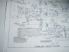
The Maggy FB as shown in the 1st schem has no affect on the amp,,, no change with it in ckt or no FB at all... The Moto bass channel schem looks very similar to the stock 175... I tried just using only the 4700R resistor as shown in the Moto FB loop, but that just produces hum/noise,,, Thinking to try the FB ckt in the dotted box, but at best that could just allow the low pass filtering... I'll post results after I try it...

Just wondering if anyone else tried to use these Moto Bass OPTs in a full range amp, as Bass is not determined by the Tx,,, The high and mid ranges are very good, and it was originally used to just produce low Z in the original amp...

Any ideas to modify the amp ckt or FB is appreciated,,,
Thanks...
 

Attachments

  • P2050023.JPG
    P2050023.JPG
    96 KB · Views: 13
  • P2050026.JPG
    P2050026.JPG
    93.9 KB · Views: 12
Last edited:
Register to hide this ad
The extra nonsense in the Motorola schematic is some sort of tone contour arrangement on some amps. Looks like others got a straight resistor. I'd go with that honestly unless you want it specifically to be used as a bass amp.

Is the output transformer secondary grounded? If that is open the feedback will not work.

Overall the feedback schemes are pretty similar, looks like the Motorola has less but if the output transformer is 8 ohm vs 4 that makes sense. The Magnavox setup with a larger value resistor (and no phase cap) is probably what you need. Other option is to just clone the whole Motorola circuit except for the RC filtering between the input tube grid and the input jacks. It looks to be relatively full range other than that. Honestly those circuits are within spitting distance of one another anyway, just a few component values differ.
 
To offer the same level of feedback as originally provided on the Mag, but with the Moto 8 ohm secondary, you would multiply the Mag FB resistor by 1.4 to give you an approximate same level of FB with the new OPT. That's an approximation and would round to 3.9K. I'd try that. (that's 3.9K split over the FB resistor that is straddled the 1000 mmF cap and the 470R).

Yes check grounding on the secondary of that new output transformer. I'm thinking it should be a nice full range transformer and should sound pretty darn good once you get ti sorted out.
 
We need a mad scientist emoji :D:lurk:

HA... The build thread is about 3 years old,, but its on here someplace!!! search "Maggy Moto"
I've used 4-5 different OPT pairs til this one popped up,,, Turns Ratio matches the original exactly,,, hard to believe!!!
 
The extra nonsense in the Motorola schematic is some sort of tone contour arrangement on some amps. Looks like others got a straight resistor. I'd go with that honestly unless you want it specifically to be used as a bass amp.

Is the output transformer secondary grounded? If that is open the feedback will not work.

Overall the feedback schemes are pretty similar, looks like the Motorola has less but if the output transformer is 8 ohm vs 4 that makes sense. The Magnavox setup with a larger value resistor (and no phase cap) is probably what you need. Other option is to just clone the whole Motorola circuit except for the RC filtering between the input tube grid and the input jacks. It looks to be relatively full range other than that. Honestly those circuits are within spitting distance of one another anyway, just a few component values differ.

I want it to be a full range 175,,, using that big Moto OPT... I don't quite understand your first sentence,,, but you know how thick I am!!!!

Yes sec is definitely grounded...

Yeah,,, the two 6V6PP schems are remarkably alike.... there is something in that Maggy ckt that isn't allowing the full Bass, I think... I recapped the Moto when I got it and the Bass was good,,,

Moto OPT is 8R,,, Moto schem shows 4700R, ,, I tried clipping a 4700 to the bottom of the K preamp cap,, just made noise... What is the phase cap? 470mmF?
Thanks fro replying!
 
To offer the same level of feedback as originally provided on the Mag, but with the Moto 8 ohm secondary, you would multiply the Mag FB resistor by 1.4 to give you an approximate same level of FB with the new OPT. That's an approximation and would round to 3.9K. I'd try that. (that's 3.9K split over the FB resistor that is straddled the 1000 mmF cap and the 470R).

So replace the 2200R with 3.9K and leave 470R?
 
Last edited:
What is the phase cap? 470mmF?
The cap across the feedback resistor. Its used to make the particular output transformer behave properly. Since the Motorola didn't use it, you probably don't need it.

Nothing in the Magnavox circuit seems to specifically limit frequency, but just copying the Motorola schematic may make life easier just because the feedback is already correct for that transformer. Same overall design, its a paraphase inverter with a pair of 6V6 tubes. About the only real change is the couple of resistors connected to the 12ax7
 
Thanks, I just put in the 3.9K,,and can remove that 470mmF( actually its a 1000mmF)... I'll try it without that cap,,,

Did you notice the FB network in the dotted box? In the schem it looks like its either or,,, I haven't tried that yet..
I could copy the Moto output circuit,,, I used the Moto PT, and eh voltage is closer to the Moto ckt(310V), than the 340V on teh 175 schem.... However 185 used 305V IIRC...
This this one is a journey rather than a destination!!!!
 
So replace the 2200R with 3.9K and leave 470R
start by removing the 470R and just put in the 3.9K.

But Moto circuit didn't have that cap, and that cap is tuned for the OPT. What is the resistor value right below the one labled 39K? Looks like 4000? (which spitting distance from 3.9K)

I would leave the circuit in that dotted box out completely.
 
Its 4700R... I figure the 3.9k I just swapped in replaces the 4.7K... I'll try removing the 1000mmF cap next... Also, notice the Maggy FB goes thru the 3300 K resistor,,, maybe I have to connect FB loop to the K pin instead of thru the resistor,,,

Think I should change the 3.9K to 4.7K?
Thanks...
 
The 3300 cathode resistor on the Mag schematic is bypassed with that 20 uF cap. So its effectively a straight wire as far as feedback is concerned.

The unbypassed portion of the cathode resistance (i.e. the "lower" resistor in the FB voltage divider) is 1500 on both amps. So the difference in applied FB level between the two amps is the FB resistor--4700 on the Moto (obtaining FB signal from the 8 ohm tap) and 2750 on the Mag, but adjusting the Mag FB for an 8 ohm tap would put the Mag FB resistor at 4500, so that's really close to the FB level that the Moto uses.

Try 3.9K, 4.3K, 4.7K...see which works best. Put a 10 KHz square wave at 1 watt output through the amp on an 8 ohm dummy load and scope the output and see what it looks like. Change the FB resistor to those suggested, and see what FB resistor makes the square wave look the best. After you settle on one, measure the level of FB applied (by measuring output w/ and w/o FB) and divide to get a ratio, then convert to dB, which is 20*Log(ratio). I bet there is about 12 dB applied with a 4.7K FB resistor.
 
OK I'll try it tomorrow,,, still have to remove the 1000mmF cap also...
Thanks for the input,,, I think it will sound pretty good,, finally!!!
 
I measured one of these Moto bass transformers - maybe not the same one but probably close. Part # 25C647057. Has an impedance peak around 35 KHz, so you may see a gain increase above 20 KHz. The feedback cap can decrease this. A few hundred to 1000 pF is likely right.
 
I measured one of these Moto bass transformers - maybe not the same one but probably close. Part # 25C647057. Has an impedance peak around 35 KHz, so you may see a gain increase above 20 KHz. The feedback cap can decrease this. A few hundred to 1000 pF is likely right.

Tom,,, Thanks for replying,,, seems the consensus is to match the Moto schem, which eliminates the 470-1000mmF Maggy cap,,, I will try it without a bypass cap, and see what it sounds like,,, also try to make the measurements as Kward described...

I thinks we discussed the OPT you have, it has a different footprint IIRC...
 
Removed the 1000mmF caps and incrementally raised the resistors to 4.7K,,, amps sounds fine now,,, the highs and mids are still fine and the bass increased to where I like it,,, looks like using the Moto FB with the Moto OPT was the ticket...

I tried to get the readings, but couldn't seem to set up test gear properly... I have a lot more experience to acquire before I can set up an amp scientifically!! So, I'll enjoy it as it is for now, and revisit the testing as I understand it better...

Thanks for all the info and help....
 
Back
Top Bottom