• The move to the new server is done. There are some software and database maintenance updates in process. This has us passing the hat around to help out. We appreciate any donations. Seriously, even a dollar helps. The payment page may be found here - https://www.audiokarma.org/support.html

Film Cap on the Power Switch/Button 2230

cemerson

Active Member
I know I've seen it here before, but I can't find it now. I have a 2230 that had an odd aftermarket switch that was installed. I've removed that and have a replacement, but every switch I've seen had a Film Cap on the side of the switch. I had a note that it should be 0.033 uF / 250 vdc film, but I don't know where I got the information or if it's correct. There's nothing on the 2230 schematics. Anyone know what I should get for this cap?

Thanks, Chris
 
Register to hide this ad
I have one open at home. I'll try to see if that cap is marked tonight if no one else comes up with the answer.
 
.033uf ..it is on the schematic .figure 20
there should also be a 2.2 meg resistor to ground from the power in side of switch .
 
You will want to use an AC rated X1 type film capacitor made specifically for this purpose. The original ones usually had an internal series 120Ω resistor, 0.1uF/300VAC is a common value. Euro models are different in this area.

Tom
 
You will want to use an AC rated X1 type film capacitor made specifically for this purpose. The original ones usually had an internal series 120Ω resistor, 0.1uF/300VAC is a common value. Euro models are different in this area.

Tom
Thanks Tom.
 
.033uf ..it is on the schematic .figure 20
there should also be a 2.2 meg resistor to ground from the power in side of switch .
Steve & Tom, I came up with a Panasonic ECQU3A104MG Film Capacitor. Let me know if there's anything wrong with using this.

Thanks, Chris
 
I checked my open 2230, and like Tom said, it has a .1uF + 120ohm, 350VAC combination component. Tom can tell you better than I can if that part is a suitable replacement and if you need to add a resistor.
Steve
 
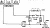
The X1 capacitor and SERIES 120Ω resistor go ACROSS the switch contacts (G001, in the diagram below). If there is a capacitor from one (or both) sides of the line to ground (or to the chassis) you need to read all about 'safety capacitors'.
Some older 2 wire line corded gear with a non-polarized plug use a 2.2 MEG Ω 1/2W resistor from one side of the line to the chassis.
(The two wires exiting the diagram below go to the Normally Open contacts of the power switch)

Tom
power.jpg
 
Good info. Thanks! I've only had to replace one broken switch, and I was able to remove the combo part from the broken switch and install it on the new one. I would have preferred a new cap, but just wasn't sure what parts to use. This will help in the future. :thumbsup:
Steve, I could have swore another thread had gone thru this, but I couldn't find it in my search. It may have been buried in another subject. My luck I'm on my third switch and the others, I did the same, just soldered the original parts to the new switch. The one I have now, the person replaced the original switch with some strange industrial push switch. It worked, but looked weird, so I just want to replace it correctly.
 
Here's a better diagram showing the switch, some models use half of the switch to independently feed the switched outlet.
The X1 capacitor and SERIES 120Ω resistor go ACROSS the switch contacts (G001, in the diagram below). If there is a capacitor from one (or both) sides of the line to ground (or to the chassis) you need to read all about 'safety capacitors'.
Some older 2 wire line corded gear with a non-polarized plug use a 2.2 MEG Ω 1/2W resistor from one side of the line to the chassis.

Tom
power.jpg
 
The X1 capacitor and SERIES 120Ω resistor go ACROSS the switch contacts (G001, in the diagram below). If there is a capacitor from one (or both) sides of the line to ground (or to the chassis) you need to read all about 'safety capacitors'.
Some older 2 wire line corded gear with a non-polarized plug use a 2.2 MEG Ω 1/2W resistor from one side of the line to the chassis.
(The two wires exiting the diagram below go to the Normally Open contacts of the power switch)

Tom
View attachment 776527
Thanks Tom, That's how I missed the resistor, it wasn't near the switch. Okay, so what I need is a 2.2 MEG Ω 1/2W resistor. Do I have to take the resistor from the ground on the switch to the chassis? That may be a stupid question, but that's how it appears to me.
 
The one I replaced was like Tom's diagram. It did not go to ground. It was between the front terminal and back terminal on one side of the switch.
 
the 120v model doesn't appear to have a resistor to ground .. just the cap with built in resistor across the switch
 
The one I replaced was like Tom's diagram. It did not go to ground. It was between the front terminal and back terminal on one side of the switch.

the 120v model doesn't appear to have a resistor to ground .. just the cap with built in resistor across the switch

What Pete said, don't add something that is not there. Check the service manual and the unit it's self. There are many variations between models.

Tom
 
Back
Top Bottom