• The move to the new server is done. There are some software and database maintenance updates in process. This has us passing the hat around to help out. We appreciate any donations. Seriously, even a dollar helps. The payment page may be found here - https://www.audiokarma.org/support.html

Filter Cap Install on 1152DC. Asking for feedback on my install

33713

Active Member
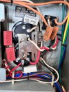
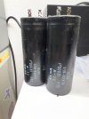
Hey Team Marantz! I was hoping a couple folks would look over my Filter Cap/Bypass Cap job in my 1152DC and it's the first time I have worked with 5 lug cans. I know I could have trimmed all the extra lugs, but it seemed cleaner to actually use them. I was flip flopping on doing it this way, but decided to move forward. Does anyone have any feedback, good bad or ugly? I am hoping to DBT this later today, but I just wanted to hear that I have not made and (visible/obvious) mistakes.

Thanks Team!

Edit: first 2 are before, second 2 are after.
 

Attachments

  • Filters 01.jpg
    Filters 01.jpg
    162.3 KB · Views: 24
  • Filters 02.jpg
    Filters 02.jpg
    168.5 KB · Views: 22
  • Filters 03.jpg
    Filters 03.jpg
    281.4 KB · Views: 25
  • Filters 04.jpg
    Filters 04.jpg
    279.4 KB · Views: 24
Register to hide this ad
So why?

Did you test the original filter caps at all? What was wrong with them in the first place? Did you even measure them? The ONLY thing that is important in electronics is the measured parameters. If good, after 48 years (the 1152 was 1978 built IIRC), those main filter caps will outlast you, me and most of the entire AK cohort.

I have a few 1152DCs I own, and seriously, the main filter caps are as good as the day they were made.

The biggest problem with the 1152/1180dc was the horizontal inverted PCB with the high gain RIAA PCB underneath the perforated grille. Dust and moisture results in a noisy/destroyed phono stage.
 
Last edited:
So why?

Did you test the original filter caps at all? What was wrong with them in the first place? Did you even measure them? The ONLY thing that is important in electronics is the measured parameters. If good, after 48 years (the 1152 was 1978 built IIRC), those main filter caps will outlast you, me and most of the entire AK cohort.

I have a few 1152DCs I own, and seriously, the main filter caps are as good as the day they were made.

The biggest problem with the 1152/1180dc was the horizontal inverted PCB with the high gain RIAA PCB underneath the perforated grille. Dust and moisture results in a noisy/destroyed phono stage.
Well, honestly, I do not know if there are in spec as I do not have a tester for caps that big. They were part of a kit from zsomeone here that sells on EBAY and I decided I could afford to change them and recap/transistor the unit, so I did. This is my 3rd Marantz, and my skills and knowledge are improving with each one (hopefully). I picture this like a jigsaw puzzle, but more complicated and I find it fun, for now.

So, I am still back at my original question. Also, I may buy a cap tester capable of reading filters accurately. Does anyone have suggestions? It seems like Atlas is the way to go?
 
Are you sure that you have those terminals wired correctly? If those are United Chemicon SMH, the datasheet has this CAUTION listed.
It looks like yours are the 5-terminal type VQT.
Did you read the CAUTION on the datasheet? "The blank terminals must not be connected to a solder trace on the PC board, but be electrically isolated from the negative or positive terminal."​
Please double check before powering on.

1792948010328.png1792948791857.png
 
Last edited:
Well, honestly, I do not know if there are in spec as I do not have a tester for caps that big. They were part of a kit from zsomeone here that sells on EBAY and I decided I could afford to change them and recap/transistor the unit, so I did. This is my 3rd Marantz, and my skills and knowledge are improving with each one (hopefully). I picture this like a jigsaw puzzle, but more complicated and I find it fun, for now.

So, I am still back at my original question. Also, I may buy a cap tester capable of reading filters accurately. Does anyone have suggestions? It seems like Atlas is the way to go?
You did the right thing. No cap lasts for 50 plus years no matter what anyone says. I second @dankik 's warning and I would first double check and even if certain use a low wattage DBT like 60W to begin with.
 
Are you sure that you have those terminals wired correctly? If those are United Chemicon SMH, the datasheet has this CAUTION listed.
It looks like yours are the 5-terminal type VQT.
Did you read the CAUTION on the datasheet? "The blank terminals must not be connected to a solder trace on the PC board, but be electrically isolated from the negative or positive terminal."​
Please double check before powering on.

View attachment 3863437View attachment 3863438
This is why I posted, thanks for chiming in! I will be reworking this. I was positioning the caps and all of the leads just kinda fell into place, I was about to trim them off, and went this way instead. I have also been doing some work, then coming back for another session and having a second look at everything with fresh eyes and I have found that to be very helpful for me, this was going to be revisited. And yes they are SMH series. I will repost when finished.
 
The wires should be connected just like the originals... to each capacitor's two terminals (+, -) with the chassis buss bar connecting the two caps (+ & -). Do not use terminals A, B and D.
 
Having another look at it. I never thought about them being there for mechanical reasons, I also never powered it up before being educated on the subject. To be fair, the instructions say to cut them off. TY
 

Attachments

  • IMG_0781.jpeg
    IMG_0781.jpeg
    352.6 KB · Views: 8
Ok, think I have it all correct now. The blue heatshrink is an attempt at insulating the extra terminals. Not really liking the result. What would anyone think about using some hot glue over them? I am assuming that this area does not really get hot? Or should I just leave them bare? Thx.
 

Attachments

  • IMG_0784.jpeg
    IMG_0784.jpeg
    440.2 KB · Views: 15
  • IMG_0783.jpeg
    IMG_0783.jpeg
    461.1 KB · Views: 14
I think I would just clip off the unused leads.
It also looks like you might have some cold solder joints. Your soldering iron did not heat up the grounding bar hot enough to flow the solder. You either need to crand up the temperature of the iron for this or temporarily unscrew it from the chassis so it doesn't act like a heat sink and try to reflow the solder. It will help if you add some flux to the joint and a bit more solder.
 
Thanks for that idea of removing the screw and isolating the bracket. I will max the temp as well. I used to have an old blue weller with a wide chisel tip on it that I can’t find that I thought would get it done better, but this other approach should work. Wiring wise, polarity and everything looks correct right? Thx
 
Wiring wise, polarity and everything looks correct right?
From what I can see, the two white wires, two red wires, and buss bar terminals are OK. I can't really tell where the two red caps are connected and the two 2.2k resistors. Also, don't know if you did anything with the wrapped wires on the strip to the right of the ground strap.

The schematic shows C003 as two 1,200uF caps. You replaced them with two 22,000uF caps almost doubling the capacitance. You could have too much in-rush current when you power on and the fully discharged caps start charging. This could put a strain on the bridge diode rectifier. Did someone else recommend upping the main capacitors to that value? Did they also recommend adding the two red caps?

1793045806009.png
1793046456095.png
 
Last edited:
Hello, and thanks again for taking a look. The original filter caps were 18,000uf, so I think we are in good shape there. A modest upgrade in capacitance. The red 225k caps are something that the seller does on his Marantz kits and probably others as well. They are referred to as bypass caps and the goal is to improve sound.

One is wired to Green/Ground/White wires and to the grounding bar, the other is connected to the red wire terminal. I think that makes sense right? The instructions say to wire them one across each filter, but I believe this effectively does that right? I did not want to do this connection under the grounding bar. Thx.
 

Attachments

  • image.jpg
    image.jpg
    319.2 KB · Views: 4
I redid the ground bar joints with it disconnected from chassis. Heat at 900 with some flux. It looks much better to me.
 

Attachments

  • image.jpg
    image.jpg
    452.6 KB · Views: 11
  • image.jpg
    image.jpg
    482 KB · Views: 10
  • image.jpg
    image.jpg
    393.2 KB · Views: 12
Back
Top Bottom