• The move to the new server is done. There are some software and database maintenance updates in process. This has us passing the hat around to help out. We appreciate any donations. Seriously, even a dollar helps. The payment page may be found here - https://www.audiokarma.org/support.html

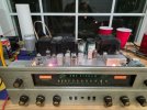
Finished rehab to a stock Fisher 500C

JimWhit

Traded San Diego for The Woodlands in Texas
Subscriber
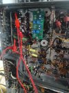
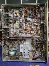
I completed my rehab thanks to all the help from this forum specially Dave. I used an online kit to upgrade the power supply, assorted capacitors, diodes, and resistors (I deviated from some of the kit instructions based on advice from the forum). I also added the Hayseed-Hamfest kit. I am still working on matching the output tubes but the stereo sounds great and completely functional with outstanding reception for my area in The Woodlands Texas. I am not sure if things could be better with IF, RF and MPX alignment and it isn't something I could do anyway.
 

Attachments

  • 20260425_203737.jpg
    20260425_203737.jpg
    191.2 KB · Views: 84
  • 20260425_205753.jpg
    20260425_205753.jpg
    108.6 KB · Views: 85
Register to hide this ad
I still need to replace the two mismatched output tubes I have old Fisher on V8 & V9, and new Tung Sol tubes on V10 & V11. So far I have:
1. Out put bias pin 5 are 0.28, 0.24, 0.32, and 0.37 V
2. Grid bias voltage pin 6 are -26, -26.78, -26.5, and -26.2
3.B+ High Voltage supply pin 3 avg 470 V DC
4 Bias Supply Negative Voltage -27.13

I took these while on the variac and will do over when I get new tubes and do it on line voltage.
 
Nice receiver. Now you can consider some of the modifications that DaveG devised. The individual bias/balance board (IBBA), the volume control buffer (this one makes a nice difference to frequency response) and Enhanced fixed bias (EFB). These are a bit of work but I think worth it. I've done a 400 and a 500c. I also built a 500c power amp only from scratch using original transformers and installed the IBBA and EFB in that unit.
Good luck,
John
 
Thanks John, I am definantly considering those mods for the future I am monitoring this unit and learning more about it before I go further.
 
An AK member @ncwalz has kindly posted his design and Gerber files for the IBBA, EFB and volume buffer boards. I had them made by JLCPCB at a very reasonable price. @RS Steve has also made some pc boards for these functions and I have used his stuffed and ready to run boards. They are very nice as well. Not sure if he still have any but wanted to mention.
 
An AK member @ncwalz has kindly posted his design and Gerber files for the IBBA, EFB and volume buffer boards. I had them made by JLCPCB at a very reasonable price. @RS Steve has also made some pc boards for these functions and I have used his stuffed and ready to run boards. They are very nice as well. Not sure if he still have any but wanted to mention.
I just installed one of my adjustable bias boards in a 800C.

20260428_203937.jpg
 
I have the screen grid resistors installed, I couldn't get the glass wire wound 7-ohm resistor to reach and all I had was this huge 1.2K ohm 10-watt resistor (the lead is exposed but it cant touch anything right now and I may replace when I make my next order. So far everything seems happy. I am getting ready to install the IBBA.
1778949122735.jpeg
 
Last edited:
I have the screen grid resistors installed, I couldn't get the glass wire wound 7-ohm resistor to reach and all I had was this huge 1.2K ohm 10-watt resistor (the lead is exposed but it cant touch anything right now and I may replace when I make my next order. So far everything seems happy. I am getting ready to install the IBBA.
View attachment 3763489
Notice in my post above yours how I do my screen buss that my 100 ohm stability resistors attach to and the two 1.2 K resistors attach to also. This was on a 800-C though, not a 400.
 
Notice in my post above yours how I do my screen buss that my 100 ohm stability resistors attach to and the two 1.2 K resistors attach to also. This was on a 800-C though, not a 400.
I couldn't reach the buss with the old one but I can attach this one to the buss. My new buss wire is one continuous wire and i added the shielding between each section I guess I was too lazy to strip it back.
 
I couldn't reach the buss with the old one but I can attach this one to the buss. My new buss wire is one continuous wire and i added the shielding between each section I guess I was too lazy to strip it back.
I have Romex that I strip and use one leg cut to length for the buss, stripping the areas where the solder connections are made. Something I have always done on my restorations; I like the very solid connections and not snaking a wire through everything like they did stock.
 
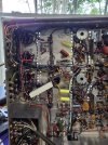
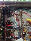
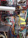
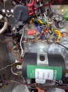
I have my board installed and I can balance both L and R channels to 0.001 but my current when measuring at pin 5 (500C) and i can only get my current to -46mA (all tubes similar). I soldered in test points at each pin, but I also confirmed the values across each resistor. The board is working in the sense that all the tubes are the same bias just way to low. These pictures show how I ran A, B, C, D, and the - bias voltage.
 

Attachments

  • 6799.jpg
    6799.jpg
    143.9 KB · Views: 11
  • 6800.jpg
    6800.jpg
    168.8 KB · Views: 11
  • 6802.jpg
    6802.jpg
    154.9 KB · Views: 11
I have my board installed and I can balance both L and R channels to 0.001 but my current when measuring at pin 5 (500C) and i can only get my current to -46mA (all tubes similar). I soldered in test points at each pin, but I also confirmed the values across each resistor. The board is working in the sense that all the tubes are the same bias just way to low. These pictures show how I ran A, B, C, D, and the - bias voltage.
I measure my bias in MVs. you must have your positive and negative leads from your meter backwards or something.
 
I measure my bias in MVs. you must have your positive and negative leads from your meter backwards or something.
It is 46 mV. I am measuring directly across each of the 10-ohm resistor? I am wondering if my bias voltage going into the board is off? I need to pole around and measure more.
 
Last edited:
While measuring voltage at pin 6 output tube V8 started to red plate (actually did red plate) when i turned my back to talk to my wife, that quick. I am taking the test point iI solder of and going to check installation of A, B, C, D, E and -V and Gnd. V8 is shot but i have a couple of substitute tubes I thought I would use just to dial in the board. I did check -V from the bias filter I believe it was -26 V and it was -20V at pin 6. I didn't get to finish so were n umber I remember when I started to poke around. Only V8 (the tube I was measuring red plated (I did have a test lead from DMM connected to it at the socket). I would greatly appreciate any advice moving forward. Thanks in advance.
 
46mv is too high, need to get that down to 35MV. What output tubes are you running?
It is 46 mV. I am measuring directly across each of the 10-ohm resistor? I am wondering if my bias voltage going into the board is off? I need to pole around and measure more.
 
I had 4 Tung Sol, one is toast now. I replace the burned Tung-sol with two old Fisher tubes on the left channel with tow Tung Sol on the right channel.

Here are some readings after balancing L and R (the numbers were bouncing up and down around 0.0)

Bias V= -26.8V
PIN 3, V8-V11 all approx. 464V
PIN 4, V8-V11 all approx. 420V
PIN 5 V8=40mV V9=42mV (these are old Fisher Tubes) V10= 37.5mV and V11=34mV (these are Tung Sol)
PIN 3 and PIN4 High?

I can change the old Fisher Tubes but I'm not going to get to 30–32 mA without tweaking negative bias supply? Open to all suggestions.
 
Last edited:
I have Romex that I strip and use one leg cut to length for the buss, stripping the areas where the solder connections are made. Something I have always done on my restorations; I like the very solid connections and not snaking a wire through everything like they did stock.
I keep spools of 18ga and 14ga tinned bus wire around for such uses.
 
Back
Top Bottom