• The move to the new server is done. There are some software and database maintenance updates in process. This has us passing the hat around to help out. We appreciate any donations. Seriously, even a dollar helps. The payment page may be found here - https://www.audiokarma.org/support.html

Fisher 200 EL-34 monoblocks with interstage transformer

OK I have been looking at my options for "robust" can caps for these and "think" I have it where I want it. I'm either going to use 3 of the 50/50uf 500V F&Ts per amp (with 3 sections in parallel to create the initial 150uF) or a slightly less expensive option is using only 2 F&Ts (a 100/100uf and a 50/50uf) with only minor effect on the voltages, ripple, and rise times.I've been messing with PSU Designer in an attempt to model the outcome.

I've also theoretically reworked the PSU to accomplish 2 primary goals:

a) to reduce plate voltages by approx 5%* in order to insure I had enough negative bias to reduce the EL34s to ~ 20 watts dissipation (about 45ma each) as the stock current was 62.5ma and 30 watts... way too hot! (especially if I strap them to triode)

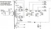
b) to move the 3000 ohm resistor that's running in parallel with the primary B+ rail (and originally used to drop 470V down to 250V necessitating the 15-watt 3000ohm ceramic ww resistor you see mounted top-side for cooling.) and place it more conventionally at the END of the string.

*actually this was an accidental byproduct of the results from PSU Designer. Even when I created the stock power supply in PSU designer, the results were quite different from what I measured on these amps (which pretty much coincided with the SAMs schematic)

While I'm not exactly sure WHY the voltages are lower, in my modded circuit I just adjusted resistances in the filters to make sure ALL voltages were lower by ~5% from spec. Then if they end up being actually a bit higher than in the simulation, they will hopefully be proportionately correct for any increase.My assumption is that the voltages are all slightly lower because I have used the MAXIMUM current for each gain stage in the PSU model, and perhaps they are not all drawing their maximums in the Fisher 200 circuit.(other than the EL34s that are running full bore!)

So below are schematics for the original power supply, the proposed modified schematic, and the results I received from PSU designer (with additional text added to explain my load taps) Does anyone see anything wrong with the changes I've made??

So what I'm hoping is someone more familiar with using PSU designer can let me know if I'm using it right and if my operating points look OK.(full schematic in 1st post)
WopOnTour
 

Attachments

  • 200ps.jpg
    200ps.jpg
    31.6 KB · Views: 91
  • 200ps_mod3.jpg
    200ps_mod3.jpg
    35.3 KB · Views: 75
  • 200ps_stockPSU.jpg
    200ps_stockPSU.jpg
    81.4 KB · Views: 50
  • 200ps_modPSU2.jpg
    200ps_modPSU2.jpg
    82.7 KB · Views: 39
  • dualsection5050.jpg
    dualsection5050.jpg
    35.4 KB · Views: 58
Last edited:
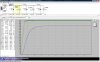
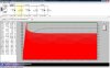
I've also posted 2 additional pics that add the amperage total (surge+steady state for 10 seconds) as an overlay to show the positive effect of my changes in stabilizing the current as compared to the stock circuit. Also note that while PSU Designer permits you to double up on the GZ34 (as used in the Fisher 200) it cant show that in the diagram other than the 2X label. WOT

This is the stock circuit voltages and current overlay (in red)

attachment.php


AND here is my modified circuit (slightly higher initital peak but lower stabilized current)

attachment.php
 

Attachments

  • 200ps_stocksurge.jpg
    200ps_stocksurge.jpg
    80.2 KB · Views: 260
  • 200ps_modsurge.jpg
    200ps_modsurge.jpg
    88.2 KB · Views: 261
Last edited:
Whoa there! - You've moved the driver to the last stage of the filter. You've also notably reduced the resistances between stages to compensate for the much higher current draw. This is playing with fire in terms of stability, if that last stage modulates the earlier stages. You need to derive the 250V from the first stage instead as was done originally, to separate it from the high-gain stages. You are unlikely to change the B+ much in this arrangement, anyways. Instead, I'd build it as it was originally, then see how it actually biases, and where the voltages fall. If your EL34s are red-plating then investigate solutions at the bias supply. Depending what diode was originally used, just switching to a modern diode may prove enough to fix your idle dissipation issues.
 
Ahh, that makes sense (I wasnt giving stability a thought as one of the 15 watt 3000 ohm resistors is skewed to 3360 so I was on a mission)- Thanks jon!
This thing is wierd with the drivers getting the lowest voltage of any stage...

ehh it gave me excuse to mess around with the PSU Designer so it's not a total loss. I'm not as worried about red plating as I am trying to get them to bias to significantly lower current. (The instructons is to set them to 125mA at 465V plate for the pair- 29 watt/tube which is just sick and wrong.)
I was thinking (if necc) of maybe just switching the bias to a bridge rectifier + a larger cap to try and get a bit more negative than -45 (which creates ~ -35V from the tube driven bias control) What you think?

I'm just going to start with just the recap then see where I stand...
Thanks for your help!!
WOT
 
Last edited:
The main reason for the low voltage is that slick transformer, which eliminates the need for a resistor load. Of course, they still draw a boatload of current. The power resistors supplying them are not especially critical in value. You just want that big driver stage to be isolated from the high-gain stages to prevent low frequency instability, so it's good that it appears early in the circuit with a few RC filters between it and the 12AX7s.

Personally, I would get it rebuilt as stock, then see how it works in practice. With the regulated bias, you may find it sufficiently adjustable once all the components are in spec. Perhaps RocJR can chime in, but I think you will be fine with the stock supply, and in the worst case scenario could change the regulator circuit slightly to allow an extra volt or two. With EL34s, it certainly won't take much to get their idle current in check.

BTW, if not for the market, I would've had to buy the pair of 200s on that auction site recently - really tormented me seeing those there. Such cool amps :yes:
 
Last edited:
WOT,

I'm with jon_s on this. Just rebuild them and get them operating correctly before you reinvent them. At that point you can measure all of their operating parameters and learn about the landmines you'll step on if you go too far outside the amp's basic design. I'll explain that in greater detail eventually.

Most of all, listen to them, for a long while, before you go to town. Get to know what they are. Stiffening the rail, maybe the ticket for you-I realize you're aiming higher than that in concept. Maybe they'll simply sound over regulated at that point? If you throw the kitchen sink at them right off then how will you know? I've always solved that problem by acquiring, over time, tightly serial numbered pairs in groups to keep a stock reference. Sure, I trust myself, but anyone can lose track, especially with X amount of investment. Depends on one's particular personality I suppose. It's impractical, maybe, but...

Anyway, why don't you get to know the amps by listening to them. If you simply swap out the selenium with a UFxxxx you'll end up with about -50 at the bottom of the pot's rotation. You'll be able to bias EL34s as cold as is reasonable. However, I think you'll have a problem with 500v caps as the B+ will rise up over that if you go that cold, 20 watts each. I did mention that Sed EL34s at 50mils per ran for years in one pair of 200's. No problemo.

It's an easy rebuild. I sure am curious about what you think of their sound. In the end, your application is way different than mine, so it's hard to say what it would mean exactly. But I'm still wonderin'

Rich
 
Last edited:
What is the end of this story; were you happy with the 200's? Did they compare favorably to your Citation? I just purchased a pair (without tubes, cages, or bottom plates) and was interested in getting some impressions of this amp before I make the investment in reconditioning them
 
I haven't read the entire thread because I'm too busy. But I will say I think you'd be crazy to modify those amps in ANY way beyond very basic power supply upgrades....like slightly upping the uF values in strategic places Those are very collectable and will sound very good as designed. Any wild mods and the value goes out the window.

My advise is if you want to be a mad scientist start from scratch don't butcher a piece of history to feed the ego....
 
Ps , had to add my 2 cents, bet these amps are long gone since its a old thread.

good eye we are probably just a bit late to save these.... I just don't get this need around here to hack things.... I really don't. If you want to be adventurous just scratch build like a real man...
 
Ps , had to add my 2 cents, bet these amps are long gone since its a old thread.
Oh I sure hope that he didn't butcher these amps.
Actually these amps are in storage and still in all original condition as shown in my photos.
I havnt spent much time on AudioKarma in recent years as I've had more than a few "life events/changes" since this thread in 2009 and simply haven't had the time to spend restoring these old girls.

Don't worry everyone, if/when I do they won't be modified significantly. (the power supply diagrams above were merely me learning how to play with PSU Designer II lol)

In fact I was thinking of getting them to someone like Jim McShane, Craig Ostby, or Mike Samra in order to insure the restoration would actually add value and not detract from them in any way.(those guys still hanging around here??)While I've done a lot of amp restos I just don't have the pedigree! ;)
Plus having not done one in over 6 years I don't even know if I can still handle it physically! The eyes, fingers and back are not what they once were!! lol

I often contemplated putting them up on eBay or Audiogon but I am too concerned with shipping them safely. I couldn't bear to see them damaged.

Even in unrestored condition they put my McShane'd Citation II to shame by my ear. In fact I sold my precious "Deuce" knowing that these were sitting on a shelf.
IMO they remain as one of the rarest, best sounding, and most interesting Fisher amps ever produced.

WopOnTour
 
Last edited:
I had a 55A which was very similar, It had a very good frequency response.
I would not be surprised if yours were the same. I had no trouble shipping it, it is built like a tank. Just pack it well.

P1010027_zpsx6o6loab.jpg

fisher%2055a2_zpsvijedjs3.jpg

P1010020s_zps0igirmzb.gif
 
Last edited:
Wow! Never knew of these before!

Yikes!

(what others said, keep stock + modern parts....)
 
I'd keep them stock and freshen them up.
BTW, quite a lot of stuff in them compared to a pair of Dyna Mk-III.
 
Old thread that never came to a conclusion. That being said I just purchased a pair and will most likely have to face the same issues.

As far as the turrets and those boards, I can make those no problem with new delrine and good quality turrets. I will be interested in a comparison with the pair of Heathkit W6-m's as they seem close as far as specs.

I was thinking of powder coating them lime green. :banana:
 
Back
Top Bottom