• The move to the new server is done. There are some software and database maintenance updates in process. This has us passing the hat around to help out. We appreciate any donations. Seriously, even a dollar helps. The payment page may be found here - https://www.audiokarma.org/support.html

Fisher 400 help

As to the original problem, invariably one of the voltage doubler caps has nearly failed open, producing the low B+ voltage. If the DC Heater/Bias supply is still (nearly) functional, then the output tubes will be biased nearly to or into a cutoff condition, the combination of which will produce little power output.

Dave
Thanks for chiming in Dave, that makes total sense. I should have checked the grid voltages and that as well but was in a hurry to just make sure the iron was good, hopefully some of these telefunkens are still useful too. I've been wanting a Fisher since I got into audio so I'm looking forward to restoring this one soon, thanks.
 
Oh. Ok. That's Mark Oppat. He's well know and also an AK member. In fact I have a message to him at his business about my needs. Thanks for sharing.
 
Oh. Ok. That's Mark Oppat. He's well know and also an AK member. In fact I have a message to him at his business about my needs. Thanks for sharing.
Is it true that he would be able to build custom pots then? I wonder about the cost and minimum order quantity.
 
As to the original problem, invariably one of the voltage doubler caps has nearly failed open, producing the low B+ voltage. If the DC Heater/Bias supply is still (nearly) functional, then the output tubes will be biased nearly to or into a cutoff condition, the combination of which will produce little power output.

Dave
Btw do you have a recommended type of diode and value of dropping resistor to replace the selenium rectifier and the other two diodes? Thanks.
 
In later versions of the 400, Fisher changed to a silicon bridge rectifier when they became available, and made no other changes in the circuit when they did. A 400 volt 4A bridge is plenty capable of the required job, and offers plenty of safety factory. Between the change to silicon and today's higher AC line voltages, the DC voltage to the heaters will definitely be higher than the published value. As a result, I usually install a 2Ω 5W resistor after the bridge but before the first filter cap. This not only lowers the output of this supply appropriately, but also maintains the original peak current demand that the supply draws from the power transformer, to prevent additional loading on it. However, while this takes care of the heater voltage, you will also want to recheck the current draw of your output tubes, as adding this resistance will also reduce the bias voltage to the output tubes, yet they are still receiving an elevated B+ level due to the higher line voltages. Therefore, their quiescent current draw will increase, necessitating adjust of their bias voltage. If you install an IBAM or IBBM circuit to provide for individual adjustment of output tube current draw, that will automatically address this issue.

Dave

 
Is it true that he would be able to build custom pots then? I wonder about the cost and minimum order quantity.

Not sure about custom pots (but maybe), but I'd have to guess the minimum order would be '1'. If I find anything different I'll let you know.
 
In later versions of the 400, Fisher changed to a silicon bridge rectifier when they became available, and made no other changes in the circuit when they did. A 400 volt 4A bridge is plenty capable of the required job, and offers plenty of safety factory. Between the change to silicon and today's higher AC line voltages, the DC voltage to the heaters will definitely be higher than the published value. As a result, I usually install a 2Ω 5W resistor after the bridge but before the first filter cap. This not only lowers the output of this supply appropriately, but also maintains the original peak current demand that the supply draws from the power transformer, to prevent additional loading on it. However, while this takes care of the heater voltage, you will also want to recheck the current draw of your output tubes, as adding this resistance will also reduce the bias voltage to the output tubes, yet they are still receiving an elevated B+ level due to the higher line voltages. Therefore, their quiescent current draw will increase, necessitating adjust of their bias voltage. If you install an IBAM or IBBM circuit to provide for individual adjustment of output tube current draw, that will automatically address this issue.

Dave
Mine is the early version with the one less IF stage, I wonder the overall sonic difference between the different revs of the Fisher 400 as I thought I read different outputs and feedback were used. I will be adding a NTC to the line side as I usually do, seems to drop a volt or two. What exactly is a IBAM or IBBM, is that like a CCS? Sounds like something I would like to install, I always like to add some way to adjust individual bias but usually have just done that on single ended amps so far with a set resistor and a pot between cathode and ground. Thanks
 
IBAM/IBBA are biasing modifications permitting the user to manually adjust bias current to the output tubes. In stock condition, Fisher provided for that adjustment via a fixed resistor. That was with the ideal/matched set of tubes in mind. Fifty+ years later, the prevailing common sense approach is to enable the user to bias the tubes so that they remain balanced over time while also keeping them operating somewhat below what is today considered too "hot." In my humble view, it is an essential modification for reliable, long term use of what can be a very expensive tube investment.

For more details, do a quick search for "IBAM." That will give you ideas re: construction, etc.
 
IBAM/IBBA are biasing modifications permitting the user to manually adjust bias current to the output tubes. In stock condition, Fisher provided for that adjustment via a fixed resistor. That was with the ideal/matched set of tubes in mind. Fifty+ years later, the prevailing common sense approach is to enable the user to bias the tubes so that they remain balanced over time while also keeping them operating somewhat below what is today considered too "hot." In my humble view, it is an essential modification for reliable, long term use of what can be a very expensive tube investment.

For more details, do a quick search for "IBAM." That will give you ideas re: construction, etc.
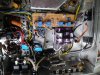
I agree, there are many slight changes that can be made to allow for these vintage units to hold up better with today's higher wall voltages. Tubes are not as cheap and the quality originals need to be preserved for as long as possible. Here is a picture of my bias adjustment board I installed in my 1800 Fisher.

20200117_105550.jpg
 
at your leisure. that's where i am planning on putting my 800b ibam when i get it built.
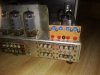
The dimensions are 3-1/8" long and 1" wide for the underneath board, the picture below is where I mounted one with test points on one of my 400's. I prefer having them under, but if it's in a wood cabinet, it sure saves work not having to take things apart.

20200128_121731.jpg
 
Back
Top Bottom