


You are using an out of date browser. It may not display this or other websites correctly.
You should upgrade or use an alternative browser.
You should upgrade or use an alternative browser.
Fisher 400 high level inputs
- Thread starter ggn71
- Start date

chadbang
Well-Known Member
I have a 500-c opened up on my bench as we speak. If it'll help, I could put up some pics of the switch and the jacks. Sometime tomorrow if there's enough interest.
Thanks, man, that would be super!
chadbang
Well-Known Member
Chad -- If you simply remove the components between the Tape Monitor input jacks and the Aux/Tape jacks, that will allow you to then have two completely separate inputs without any bleed over between them. However, the two inputs will still have distinctly different sensitivity levels, with the Tape Monitor input requiring a higher volume setting to achieve the same sound level from an otherwise equal input signal level presented to both inputs.
In my thread where I modified the 400, I addressed this problem as part of a whole suite of areas I addressed in this receiver, electrically moving the switch in the circuit so that the Tape Monitor input now has the same sensitivity level as the Aux input does. Of course, the bleed over components were removed as well.
You could easily remove the bleed components, and also electrically reconfigure the Tape Monitor switch as I did in that thread. The underside of the 400 can look daunting to those tackling such issues for the first time, but in this case, its mainly just a rewiring exercise, requiring no new components to be installed.
Dave
Thanks, Dave, I will go check that thread out. I was so baffled by the lower output I bought a new cartridge for my second table! Duh! I didn't even think about switching around cables because a line-in has ALWAYS fuctioned like a line-in on modern units. I was also sweating there was something wrong iwth my Fisher!

Guys. Go to Dave Gillespies 400 rebuild thread (the one that had like 6-8 revisions to the schematic done by eduarsan). In it he details how to remove the bleeder circuit from the Aux/Tape circuit to separate the AUX and TAPE Monitor. Plus some other stuff that will make the 400 scream like a 41 Willy's gasser.
Who knew? I guess I'll be popping over to that rebuild thread to see what has to be done. Thanks Larry. And you too Dave, again :thmbsp:
I re-read Dave's 400 thread (and tried to understand it  ) and came away with the conclusion that it is possible to have THREE auxiliary inputs: The original AUX, the adjacent TAPE/MON jacks, AND the TAPE HEAD jacks.
Correct??
) and came away with the conclusion that it is possible to have THREE auxiliary inputs: The original AUX, the adjacent TAPE/MON jacks, AND the TAPE HEAD jacks.Correct??

You got it!
FWIW -- I hardly expect everybody to understand all of the various elements addressed in that thread -- or even to want to understand it. However, there is so much stuff put out there on the web today that either has absolutely no scientific basis, is explained with scientific gibberish, or is offered up under the "trust me" category. Also, there are many modifications offered for concerns that show the author really does not have a total understanding of the technical concepts involved, and ultimately ends up offering a modification that is actually detrimental to the performance of the original design. Therefore, I try to do everything I can to keep a wide berth between the modifications I offer, and those offered with these other types of explanations or designs. As a result, I always try to explain in detail all that I do with a what, where, why, and how approach -- hardly to sound impressive -- but to offer a factually based explanation for each modification, and to help those understand who are interested in the more technical side of their equipment. Therefore, I will always try to explain exactly what the issue is being addressed, where it is located within the design, why it is a potential concern, and how it might better be resolved with a new approach, while still keeping the basic integrity of what the unit was designed to be in tact.
Dave
FWIW -- I hardly expect everybody to understand all of the various elements addressed in that thread -- or even to want to understand it. However, there is so much stuff put out there on the web today that either has absolutely no scientific basis, is explained with scientific gibberish, or is offered up under the "trust me" category. Also, there are many modifications offered for concerns that show the author really does not have a total understanding of the technical concepts involved, and ultimately ends up offering a modification that is actually detrimental to the performance of the original design. Therefore, I try to do everything I can to keep a wide berth between the modifications I offer, and those offered with these other types of explanations or designs. As a result, I always try to explain in detail all that I do with a what, where, why, and how approach -- hardly to sound impressive -- but to offer a factually based explanation for each modification, and to help those understand who are interested in the more technical side of their equipment. Therefore, I will always try to explain exactly what the issue is being addressed, where it is located within the design, why it is a potential concern, and how it might better be resolved with a new approach, while still keeping the basic integrity of what the unit was designed to be in tact.
Dave
Dave:
As I and countless others have previously stated numerous times, your invaluable input as well as the detailed and logical approach to explaining matters Fisher is a godsend to those of us here and beyond. Speaking for myself, but I'm sure others as well, I stand in awe not only to the depth of your knowledge but also, and to me, more importantly, the unselfish and unconditional way you impart it to those of us who are interested. Kudos to you for that :thmbsp:
Now as far as my comment about "understanding." Well, it was kinda a half joke to myself. In truth, as I was going through the thread trying to pinpoint the parts that were specific to the issue at hand, I was tickled by the fact that I actually could understand a lot of what was being discussed, evidencing the fact that a lot of water has passed under the bridge since I found that first Fisher in the garbage. I will not hesitate to say that my current level of "understanding" is due to the likes of you, Larry, Don, Bruce (and others for sure, even Tony!) With that said, it is my hope to contribute to the OP's resolution of the AUX stingy state of his current Fisher and continue the helpful tradition that you so amply demonstrate.
As I and countless others have previously stated numerous times, your invaluable input as well as the detailed and logical approach to explaining matters Fisher is a godsend to those of us here and beyond. Speaking for myself, but I'm sure others as well, I stand in awe not only to the depth of your knowledge but also, and to me, more importantly, the unselfish and unconditional way you impart it to those of us who are interested. Kudos to you for that :thmbsp:
Now as far as my comment about "understanding." Well, it was kinda a half joke to myself. In truth, as I was going through the thread trying to pinpoint the parts that were specific to the issue at hand, I was tickled by the fact that I actually could understand a lot of what was being discussed, evidencing the fact that a lot of water has passed under the bridge since I found that first Fisher in the garbage. I will not hesitate to say that my current level of "understanding" is due to the likes of you, Larry, Don, Bruce (and others for sure, even Tony!) With that said, it is my hope to contribute to the OP's resolution of the AUX stingy state of his current Fisher and continue the helpful tradition that you so amply demonstrate.
Thanks, man, that would be super!
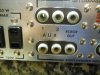
OK, so here we go: Right at the AUX and TAPE MON jacks there are 2 pairs of resistors/caps valued at 330K and 120pF. Both pairs bridge the jacks. They all go bye bye.
Tracing the existing wiring in my 500-c (I'm sure it's the same in the 400):
AUX jack: right ch gr/wht wire to sel switch;
left ch bk/gr wire to sel switch.
TAPE/MON jack: right ch red/wht to TAPE MON switch;
left ch blk/red to TAPE MON switch.
Now this is where I'm stuck. Doesn't the TAPE MON switch have to be re-wired? I've read thru the thread but, for the life of me, I'm not feeling it. Help?
Attachments


Not -- Thanks for the kind comments -- which are truly appreciated -- but I'll tell you, the real joy of this forum is the interaction of ALL of us -- those new ones just starting out, to those with more experienced understanding. I see some of the clean ups and rescue efforts, new ideas or sources and think gee wiz, I wish mine looked like that, or I'm so glad to know about that!
The bottom line is a total appreciation for the products that Avery produced, and the fact that they continue to produce such satisfaction some 50+ years later.
Good luck to all Fish owners!
Dave
The bottom line is a total appreciation for the products that Avery produced, and the fact that they continue to produce such satisfaction some 50+ years later.
Good luck to all Fish owners!
Dave
Not -- Removing the components you mentioned will eliminate the bleed circuit.
The Tape Monitor switch will in fact have to be rewired. I've got some chores to do at the moment, but later on today, I'll try to post a step by step for you guys on how to rewire the switch. Doing so will make the Tape Monitor input have the same sensitivity as that of the Aux input setting, with of course no bleed through due to the components being removed you previously mentioned.
Dave
The Tape Monitor switch will in fact have to be rewired. I've got some chores to do at the moment, but later on today, I'll try to post a step by step for you guys on how to rewire the switch. Doing so will make the Tape Monitor input have the same sensitivity as that of the Aux input setting, with of course no bleed through due to the components being removed you previously mentioned.
Dave
To electrically move the Tape Monitor switch as I did in my 400 modification thread, you will need to perform the following steps in each channel. With the unit turned upside down, and the rear panel facing you:
1. At the rear jack section, remove the jumper connecting the Reverb In and Recorder Out jacks. On one of these jacks, there is a 680k resistor connected to ground. This resistor must remain connected to the Reverb In jack if not already. If it was on the Recorder Out jack, it must be moved over to the Reverb In jack. The shielded cable connected to the Recorder Out jack remains connected to that jack.
2. Draw a new length of shielded cable from the jack area, up to around the Tape Monitor switch area. At the jack area, connect the hot and ground leads of this cable to the Reverb In jack hot and ground terminals respectively.
3. At the Tape Monitor switch, remove the lead/components connected to the center terminal of this switch for the channel being worked on, and connect the lead/components to the hot lead of the new shielded cable coming from the Reverb In jack. Isolate the ground lead of the shielded cable on this end of the cable.
4. At the selector switch, identify the 470K resistor (with either a 18 or 24 pf cap in parallel with it) feeding the signal to V10 for the channel being worked on. Disconnect this resistor and capacitor network from the selector switch terminal it is connected to.
5. Connect the free end of the network freed up in #4 above to the center terminal of the Tape Monitor switch.
6. Connect the terminal on the selector switch where the network of #4 above was removed from to the bottom terminal of the Tape Monitor switch for the channel being worked on. With the unit upside down, this will be the terminal closest to you.
And that is it. The sensitivity of the Tape Monitor input jack will now be the same as that of the Aux input jack. Also, the Recorder Out jack signal will now be of the same level as the chosen high level input (or output of the phono preamps) represents. The jack area is very tight to work in, so patience is required to do a neat job without burning the wiring up in that location with your soldering device.
Also, try to keep as much distance as possible between the wiring/terminals on the right side of the Tape Monitor switch and the wiring/terminals on the left side of the speaker on/off switch.
If the impedance connection leads are not used on the rear speaker connection posts to allow the speaker on/off switch to operate, then this is of no concern. However, if these leads are connected, and the wiring of the two switches is too close, then feedback can occur at very high volume settings when the treble is advanced to full on. Maintaining adequate distance will prevent this from happening.
Dave
1. At the rear jack section, remove the jumper connecting the Reverb In and Recorder Out jacks. On one of these jacks, there is a 680k resistor connected to ground. This resistor must remain connected to the Reverb In jack if not already. If it was on the Recorder Out jack, it must be moved over to the Reverb In jack. The shielded cable connected to the Recorder Out jack remains connected to that jack.
2. Draw a new length of shielded cable from the jack area, up to around the Tape Monitor switch area. At the jack area, connect the hot and ground leads of this cable to the Reverb In jack hot and ground terminals respectively.
3. At the Tape Monitor switch, remove the lead/components connected to the center terminal of this switch for the channel being worked on, and connect the lead/components to the hot lead of the new shielded cable coming from the Reverb In jack. Isolate the ground lead of the shielded cable on this end of the cable.
4. At the selector switch, identify the 470K resistor (with either a 18 or 24 pf cap in parallel with it) feeding the signal to V10 for the channel being worked on. Disconnect this resistor and capacitor network from the selector switch terminal it is connected to.
5. Connect the free end of the network freed up in #4 above to the center terminal of the Tape Monitor switch.
6. Connect the terminal on the selector switch where the network of #4 above was removed from to the bottom terminal of the Tape Monitor switch for the channel being worked on. With the unit upside down, this will be the terminal closest to you.
And that is it. The sensitivity of the Tape Monitor input jack will now be the same as that of the Aux input jack. Also, the Recorder Out jack signal will now be of the same level as the chosen high level input (or output of the phono preamps) represents. The jack area is very tight to work in, so patience is required to do a neat job without burning the wiring up in that location with your soldering device.
Also, try to keep as much distance as possible between the wiring/terminals on the right side of the Tape Monitor switch and the wiring/terminals on the left side of the speaker on/off switch.
If the impedance connection leads are not used on the rear speaker connection posts to allow the speaker on/off switch to operate, then this is of no concern. However, if these leads are connected, and the wiring of the two switches is too close, then feedback can occur at very high volume settings when the treble is advanced to full on. Maintaining adequate distance will prevent this from happening.
Dave
Last edited:
Thanks Dave. I'll study these instructions and hopefully get to it sometime tomorrow.
Quick question, (probably first of several): Is this rewire mapped out in the schematic Luis drew up? I'd like to reference it if it is.
Thanks!!
Quick question, (probably first of several): Is this rewire mapped out in the schematic Luis drew up? I'd like to reference it if it is.
Thanks!!
Not -- For the most part, yes. But because the Reverb jacks were also re-purposed in that modification exercise, they won't appear on the revised schematic that Luis drew up for my Modified 400, as they appear on the original 400 schematics. The steps I gave you assume that the Reverb jacks are still connected for their original intended purpose.
Good luck with it!
Dave
Good luck with it!
Dave
OK, thanks. But question on #6:
From the now free selector switch terminal, I connect 2 wires, one to the right channel side of the TAPE MONITOR switch , another to the left side?
From the now free selector switch terminal, I connect 2 wires, one to the right channel side of the TAPE MONITOR switch , another to the left side?
No. From the freed up selector switch terminal, there will be one wire connected, which goes over and connects to the bottom terminal (top terminal facing you with the unit upside down) of the Tape Monitor switch for the channel you are working on. That will be the second wire connected to that Tape Monitor switch terminal, as there is already the hot lead of a shielded cable connected there, which must remain there.
Remember, you are doing this entire set of procedures in each channel separately, so step #6 will be performed a second time from a different selector switch terminal over to the bottom terminal on the other side of the Tape Monitor switch when you are doing the modification in the other channel.
The paragraphs after the one for step #6 are general comments regarding the whole of the modification -- not a continuation of step #6 itself.
I hope this helps!
Dave
Remember, you are doing this entire set of procedures in each channel separately, so step #6 will be performed a second time from a different selector switch terminal over to the bottom terminal on the other side of the Tape Monitor switch when you are doing the modification in the other channel.
The paragraphs after the one for step #6 are general comments regarding the whole of the modification -- not a continuation of step #6 itself.
I hope this helps!
Dave

eduarsan1
Luis Eduardo Sanchez
OK, thanks. But question on #6:
From the now free selector switch terminal, I connect 2 wires, one to the right channel side of the TAPE MONITOR switch , another to the left side?
Not
In the Dave's thread (improving the fisher 400) I post some pictures in very high quality, where are the mods in the tape monitor switch as Dave explains upper lines. Take a look on it, may be helps on your mods without modified reverb jacks!
Regards
Luis
Last edited:
Remember, you are doing this entire set of procedures in each channel separately, so step #6 will be performed a second time from a different selector switch terminal over to the bottom terminal on the other side of the Tape Monitor switch when you are doing the modification in the other channel.
Dave
That's why I ask the question. If I'm understanding correctly, there are TWO sets of 470k/caps at the selector switch. Only one set is obvious to me so it seemed odd. The "missing" set is likely buried on the other side of the switch so I'll put better light on it. Thanks!
Never mind, rook mistake. Unlike the first pair, it's not "on" the selector switch but on the terminal strip between V-14 & V-15(I'm modding a 500-c.)
OK, in a couple of hours I'll scrub up and head into surgery
And Luis: Thanks for the link to your pics; they are exceptionally clear. Although the physical layout of the 400 is different from the 500-c, I can clearly see where you wired both 470k/cap networks to the slide switch. Thanks!
OK, in a couple of hours I'll scrub up and head into surgery
And Luis: Thanks for the link to your pics; they are exceptionally clear. Although the physical layout of the 400 is different from the 500-c, I can clearly see where you wired both 470k/cap networks to the slide switch. Thanks!
Last edited:
So glad it's working well for you!
The Tape Monitor modification and removal of the Aux/Tape Monitor bleed circuits were just a couple of the common sense improvements undertaken in that thread, to help bring the 400 (or any of the Fisher stereo receivers) into the 21st century, while still letting it retain the integrity of what it is: A wonderful Fisher receiver.
Now you can enjoy two separate high level inputs with both having the same Aux level sensitivity. I think I also posted in that thread (or it got reposted maybe) how you can also turn the tape head position into a third high level input if needed.
Congrats on the successful execution!
Dave
The Tape Monitor modification and removal of the Aux/Tape Monitor bleed circuits were just a couple of the common sense improvements undertaken in that thread, to help bring the 400 (or any of the Fisher stereo receivers) into the 21st century, while still letting it retain the integrity of what it is: A wonderful Fisher receiver.
Now you can enjoy two separate high level inputs with both having the same Aux level sensitivity. I think I also posted in that thread (or it got reposted maybe) how you can also turn the tape head position into a third high level input if needed.
Congrats on the successful execution!
Dave