• The move to the new server is done. There are some software and database maintenance updates in process. This has us passing the hat around to help out. We appreciate any donations. Seriously, even a dollar helps. The payment page may be found here - https://www.audiokarma.org/support.html

Fisher 400 restoration question

getone

Member
Dear Members,

I was given a Fisher 400 receiver from a colleague of mine. According to him it worked 20 years ago. After reading many threads here and elsewhere and before plugging the amp in, I started a restoration project with the kit from Metalbone.

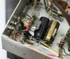
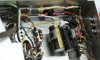
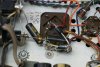
I've done the first round of replacements. Please look at the pictures and let me know if you see something very wrong before I slowly bring her up with a variac (after I put back all the tubes)

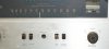
Also, a switch in the front is missing. Can I still evaluate if the amp is working roughly.

Thanks!
 

Attachments

  • DSC04923.jpg
    DSC04923.jpg
    50.3 KB · Views: 110
  • DSC04924.jpg
    DSC04924.jpg
    71.6 KB · Views: 99
  • DSC04925.jpg
    DSC04925.jpg
    61.1 KB · Views: 89
  • DSC04927.jpg
    DSC04927.jpg
    72 KB · Views: 86
  • DSC04928.jpg
    DSC04928.jpg
    60.2 KB · Views: 91
  • DSC04930.jpg
    DSC04930.jpg
    36.8 KB · Views: 81
Register to hide this ad
It looks like your two 1000uf caps for the bias supply are tied together incorrectly. One positive goes to ground, the other goes to the rectifier and then to the 15ohm resistor. The negative leads are tied together and provide the -17VDC needed. I'm commenting only because I'm assuming you are using two identical caps there and both negative leads should have the gold negative stripes on the outside of the caps.
 
Thank you for the response. I did solder the two negative leads (indicated by the golden line) together neatly. However, when I was pushing the caps down into the clip of the old can capacitor, things twisted a bit.

Thank you again for the reply.
 
The only thing I would suggest is use of heat shrink tubing on the solder joints that are close to each other or a bulkhead. Vibration or movement by someone working in there with power on can cause Fourth of July or New Years activity! SAFETY 1st. Other wise it looks like you are on the right track.

Oh yeah one more suggestion for your wallet. Even tho the Muse or black gate caps are good caps, they are un-necessary in non signal path areas (power supply). Save yourself some dinero and use Nichicon UPW series for the power supplies and UKL for low noise use in the signal path. These are proven to work well in audio applications. then you can use the muse if you want in the direct signal path where required by size and type. 2.2uf and below you can use Panasonic ECQ Stacked film instead of electrolytics. Watch the size tho above 1uf.
 
OK, so I did power it up with a variac. I left the tubes in. At the end all tubes lit up and other lights were on. Next I connected speakers and hear nothing.

I did some voltage measurements:

At C74 I measured -19 V and at CR1 I measured +440 V (schematics calls for 395 V).

In your opinion, what are the next parts that I need to replace to see if the unit is worth the further effort. How would I test the output transformers without taking them out?

Of course, I don't know the status of the tubes. I called all the local TV repair shops and nobody has a tube tester any more. But if one or two tubes are bad I should hear something from at least one channel, right?

Thanks!
 
Locate a local Ham Radio club. Most of the members work on their own equipment. Soemone is sureto have a tube tester.

To check out the output transformers you'll need to disconnect the leads and check the individual sections for shorts or opens. You have service manual with a schematic, right??
 
Thank you for the info. I have the service manual and the schematics.

Here are some more tests:

For V13 and V14 at pin 9 the voltage is +395

For V15 and V16 at pin 9 the voltage is 0.

After power off, removal of the output tubes the resistance between pin 9 of V15 and V16 is infinite.

I will desolder the leads and take the T2 out. Check the wires and measure again. I hope I do not have a bad transformer.

Also, I moved some 12ax7 tubes around and got a very faint signal from AUX in the other channel. Good sign, I guess. At this point my thinking is:

Get that one channel working using the AUX input. I will replace the coupling caps and test again to start with.

Do you have any other suggestions?
Thanks!

Gabor
 
Get the 2nd channel working at the same time. That's the best course at this point. You're looking at probably $200+ worth of tubes to replace just the 12ax7's and the 7868's. GET THEM ALL TESTED before doing anything else.

And DO NOT POWER IT UP WITHOUT a LOAD! Load meaning speakers, or dummy loads of 8oHm/50W resistors across the speaker leads. Running it without loads will kill the other transformer really quick.

The high B+ is due to the one side being dead. It'll come down when the other transformer starts working.
 
Sorry for the silence, I was away for two weeks.

I finally went back to the project and replaced all coupling capacitors. Could not find anyone to test the tubes, so I gave a shot. The result: great sound from one speaker.

The high B+ is due to the one side being dead. It'll come down when the other transformer starts working.

Please tell me the mysterious meaning of "other transformer starts working"

Is there any hope that I can "revive" the transformer or does it need to be replaced. Rewinding is way too expensive, I think.

Thanks!
 
Meaning the problem with the transformer is fixed. What is the voltage from the center tap to the transformer? Look at the schematic and trace it back to the junction of the other transformer and make sure you have input voltage on the primary side 1st. If you have voltage there then turn it off and measure resistance from the center tap to pin 9 on V15 and V16. If you got an infinite reading from Pin 9 to pin 9 on V15 and 16 that means the winding is open. I'd CAREFULLY open the transformer and follow those leads up to where they connect with the winding. Also check the center tap lead to the winding. If they are intact, check each lead from the end to the winding connection with an ohm meter. You should get close to 0 ohms. Then check the winding where the wires from V15 and 16 connect. If it's still open, send it to Heyboer. They'll build a new one with the old endbells for about $100 or so. A lot cheaper than other places that start at $200-$250 just for a rewind. You'll get a totally new transformer meeting the original spec and then some (larger wire usually). And it'll look totally stock as they are using your endbells.

Other than trying to find an operable factory transformer on Ebay, this is the cheapest option.
 
Last edited:
Dear Larry,

Thank you for all your help. While I am waiting on the output transformer I thought I will do the re-stringing of the radio. It seems that it is quite difficult to turn the drum (to which the string attaches). After re-stringing the string just slips on the tuning knob. How should I try to grease the axle ? Most part of it is under the metal housing.

Thanks again!
 
The "axle" or Tuning Capacitor is geared down just inside the shield box. It's supposed to be somewhat tight.

How tight did you make the dial cord? It has to be fairly tight with the spring on the one side expanded about 1/8 to 1/4". You might put a drop of oil VERY CAREFULLY on the pulley shafts for the plastic pulleys.

How many turns around the shaft for the tuning knob. 3-4 turns is required.

What kind of cord did you use?

I'd get some straight beeswax or Violin BOW Rosin 1st and apply that to the cord on either side of the Knob shaft before opening up the shield box and mucking around the tuner cap. You screw that up by bending a fin, and it's a good chance it's gonna be a doorstop. special procedures and cleaners/lubricants for the tuner cap. If your eyesite isn't that good or your hands aren't steady, I'd not recommended working in there. Take it to a shop and have them free it up and then align it (tuner and MPX).

If you're game, there is a thread in the Tuner forum on how to clean a tuner cap. BE EXTREMELY CAREFUL. Brush up against one of the fins and the whole thing is out of alignment. It is what is called an AIR GAPPED CAPACITOR. The distance between the plates or fins is preset. Dirt, dust, or other contaminants will change the value. Use only an ELECTRONICS CLEANER that states "NON- RESIDUE" on the can. Use DeOxit only on the end of a toothpick and touch the bearings and ground spring clips. Do NOT Touch the fins. Once Lubed and cleaned, put the cover on BEFORE turning the Big Pulley. There will be some resistance.

Be Careful and TAKE YOUR TIME.

Larry
 
Well, I have bought a string from Antique Radios (http://www.radioantiques.com/supplies.html) and it did the job.

I have also got the OT and installed it. There is a very loud "buzzer" kind of sound coming from that channel, while the other channel works great now. If I swap v12 and v11 I get the same result. If I remove V12, there is no sound from that channel. To test the system further here is what I did:

I have removed V11 and V12 and checked the voltages at the pins. At V11 and V12 I read nearly the same for each pin. I did not want to put the tubes back and check the voltages, as I was afraid to destroy the OT. Instead I did the following:

I disconnected C62, C63, C64 and C65 from going to the power tubes and routed C62 and C63 towards T2.

Removed V11 and tested the sound. It was OK. I guess it means that V15, V16 and T2 are OK.

Next I reconnected C62, C63, C64 and C65 according to the schematics (original wiring).

Then, I have swapped the cables at pins 2 of the volume pot. Again, the noise came from the speaker connected to T2. I guess this means that the signal is OK up to the volume pot.

Taken together there is not much left around V12. Nothing seems suspicious. The resistors seem OK and read the same values as around V11.

Therefore I think it is the 7 pF cap on v12.

I have ordered a 7 pF 50V ceramic disc cap. Interestingly, the part list does not match the schematics in my version of the service manual, but the cap reads 7 in the unit.

Please let me know if you have suggestion how to proceed.

Thanks!

Gabor
 
Gabor -- There is a very good possibility that the rewound OPT has the plate leads reversed from the rewinding process. Try reversing the plate leads at the output tube sockets on that transformer, and there is a good chance that will solve your problem. If the leads are switched, the negative feedback becomes positive, making the output stage an oscillator, creating the noise you hear. Reversing them will make the NFB negative again.

Good luck with it!

Dave
 
Gabor -- There is a very good possibility that the rewound OPT has the plate leads reversed from the rewinding process. Try reversing the plate leads at the output tube sockets on that transformer, and there is a good chance that will solve your problem. If the leads are switched, the negative feedback becomes positive, making the output stage an oscillator, creating the noise you hear. Reversing them will make the NFB negative again.

Good luck with it!

Dave

Are the plate leads those that run to pin 9 of v15 and v16? I am learning on the way, don't know most of the terminology.

Thanks!
 
yes. Put everything back to original from post #13. Reverse the plate leads on pin 9. and try again. Like Dave said you've probably got them reversed and the OPT is acting like an oscillator.

Keep us posted.

Larry
 
so much to learn

Thank you for all your replies. I did switched around the leads from T2 on pin 9 of v15 and v16. That WAS the issue. So much to learn.

Now I have a receiver that works excellent. Thank you for all your support!

I will summarize my experiences restoring this piece of history in a new thread sometime soon.

Thank you again!

Gabor
 
I did a spice simulation in which I got the feedback out of phase by switching the transformer leads. The output was an oscillation like you describe. Sounds like you did that for real.

The 7pf ceramic cap is there to prevent a high frequency runaway oscillation. You would never hear it but would watch your output tubes redplate. Be sure they are there before you power up the unit, they are essential. They are not on every schematic and are not always 7pf but they must be in place.
 
Back
Top Bottom