• The move to the new server is done. There are some software and database maintenance updates in process. This has us passing the hat around to help out. We appreciate any donations. Seriously, even a dollar helps. The payment page may be found here - https://www.audiokarma.org/support.html

Fisher 400T Tune o Matic wiring help

Jeff Gniffke

New Member
Hope I’m in the right place to ask for assistance with a Fisher 400T. In restoring a box of parts, all has gone well except connecting the Tune o matic unit to its associated board. Following the schematic I’ve gotten close but do not have the use of the main tuning pot, I do have use of 1-5 pre sets. Anyone have one of these guys that could photograph the connections? It’s possible the Fisher 250T is the same...the schematic seems to indicate that. Thank you for any help!

Jeff
 
Register to hide this ad
The FM on the 400-T is ALL Solid State Electronic by way of Varactors. That Tuning capacitor in the Box is for the AM BAND. There is a Rheostat on the back, that should be cleaned with Contact cleaner or DeOxit), and the IIRC.01uf 250V cap changed out as it's the Variable Cap /variable resistance for the tuning front end.. As for the wiring, My 250-T is in the Storage Shed and my 400-T is buried in the garage.
 
Thanks Larry!...I replaced the output transistors....one side had burnt resistors in the I put in an OEM P-2036 pre-driver/driver board ...everything is doing pretty well thus far...I have to find this cap you mentioned
 
Last edited:
Look on the back of the metal tuning box in the center. There will be a plastic rheostat housing with a blue/green(this is color of all the one's on my 250-T, 400-T, 500 TX's.) cap on two connections.
 
Yes! Did some cleaning and deoxit...the cap is a .33 on my machine though it is light green/blue....C10 on my tuner section schematic...this rheostat is interesting.
 
And that's why I prefaced the value with IIRC. Replace the .33uf. Those green/blue have a tendency to leak electrically. The rheostat varies the voltage on the varactor circuit and the board, folds, spindles, and multilates it into a listenable sound thru Common core math and revisionist history, with a very slight dose of :whip:60's Berkeley liberalism.
 
Thank you Larry... any other tips on the 400T? First time time dealing with solid state...my other gear is tubed Fisher X100, 800 and 101R...and many many tubed radios....30’s,40’s and 50’s

I had to read what a varactor diode was....and does. I had to study what the power transistors did...why were they in sets of two etc
 
Last edited:
Go slow and steady. Caps are caps, whether they're in Tube or Solid State. Resistors the sam ting. I agree transistors are a PITA!!!
 
As I recall I just stuffed some MJ21193G and 94G in mine and let'er Rip. Way Overkill, but they were in my stash, soooo...................
 
Ha! Yes the ones! If I understand all the engineering data on the sheets they indeed were better than originals...sound and readings are good!
 
Putting 93's and 94's in a 400-T is like hiding a LS-7 in a Corvair. They'll loaf all day long and twice on Sundays.
 
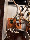
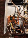
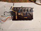
I know it’s an old thread but I could have used the wiring help on the tune o matic. The schematic is not great and potentially misleading with the way it is labeled. So after a few hours of studying and Tracing the wires here are some pictures of the finished product.

First picture is of the external wires from the to the tune o matic circuit board.IMG_4496.jpeg

The next picture is of the wires from the tune o matic tuner the the circuit board.
IMG_4497.jpeg
Finally here is a picture of the back of the detached tune o matic for reference. I hope this helps anyone who might need it in the future.IMG_4495.jpeg
 
Back
Top Bottom