• The move to the new server is done. There are some software and database maintenance updates in process. This has us passing the hat around to help out. We appreciate any donations. Seriously, even a dollar helps. The payment page may be found here - https://www.audiokarma.org/support.html

Fisher 500B (pre-serial #20001)

smittola

New Member
Hey Fisher Guru's:

I'm starting to rebuild an early model Fisher 500-B (serial # 11279B). I can't locate any schematics for the
pre-serial # 20001. I've rebuilt six 500B (All serial # 20001+ units). This is my first time working on a very early 500-B. Two questions please:

Does anyone know where I might find a schematic of this early model?

Are there any real differences, besides the placement of the 7791 tubes, that I should be aware of?
 
Register to hide this ad
Does your 500B have the output tubes forward of the output transformers or are the output tubes on the back edge of the receiver?

I haven't seen a schematic for the very early version. If it were me, I'd use the schematic that's available and just be careful and cross check each component that I want to verify or replace.

I recently restored a 500B (version with the output tubes on the back) and did a total rebuild of the power supply, replaced all electrolytic caps, replaced the coupling caps, tested all tubes, cleaned all controls/switches, replaced the selenium rectifier, checked all the resistors and replaced some that were out of spec; and a bunch of repairs for misc items such as replacing the dial cord which was broken. I also did all the safety mods and a couple of improvement mods. What you do depends on the condition of the unit but you could take it as far as you desire. My 500B sounds glorious now, but I'm not quite done yet. Good luck.
 
Electrically, the schematics should be similar if not the same. It's really just placement of the trannies and the output tubes. Still, I'd note any changes and make appropriate notes in the later schematic.
 
Does your 500B have the output tubes forward of the output transformers or are the output tubes on the back edge of the receiver?

I haven't seen a schematic for the very early version. If it were me, I'd use the schematic that's available and just be careful and cross check each component that I want to verify or replace.

I recently restored a 500B (version with the output tubes on the back) and did a total rebuild of the power supply, replaced all electrolytic caps, replaced the coupling caps, tested all tubes, cleaned all controls/switches, replaced the selenium rectifier, checked all the resistors and replaced some that were out of spec; and a bunch of repairs for misc items such as replacing the dial cord which was broken. I also did all the safety mods and a couple of improvement mods. What you do depends on the condition of the unit but you could take it as far as you desire. My 500B sounds glorious now, but I'm not quite done yet. Good luck.
 
Does your 500B have the output tubes forward of the output transformers or are the output tubes on the back edge of the receiver?

I haven't seen a schematic for the very early version. If it were me, I'd use the schematic that's available and just be careful and cross check each component that I want to verify or replace.

Thanks for your reply. I attached a copy of the layout of my early 500-B. Layout of older 500B.png
 
Last edited:
Electrically, the schematics should be similar if not the same. It's really just the placement of the trannies and the output tubes. Still, I'd note any changes and make appropriate notes in the later schematic.

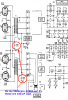
Thanks, Larry. So far, I have only come across one small difference in the circuit. See the uploaded file. I would guess any of these small changes were made by Fisher as they fine-tuned their original engineering designs.
 

Attachments

  • caps difference.png
    caps difference.png
    151.4 KB · Views: 17
Back
Top Bottom