• The move to the new server is done. There are some software and database maintenance updates in process. This has us passing the hat around to help out. We appreciate any donations. Seriously, even a dollar helps. The payment page may be found here - https://www.audiokarma.org/support.html

Fisher 500B restoration questions

Raccoon1400

Super Member
I'm a good chunk of the way through a Fisher 500B restoration and I have a few questions. I did a Fisher 400 for the same client a few months ago, and am working from the same instructions. This time I'm not cleaning up another shop's mess.

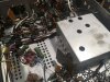
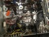
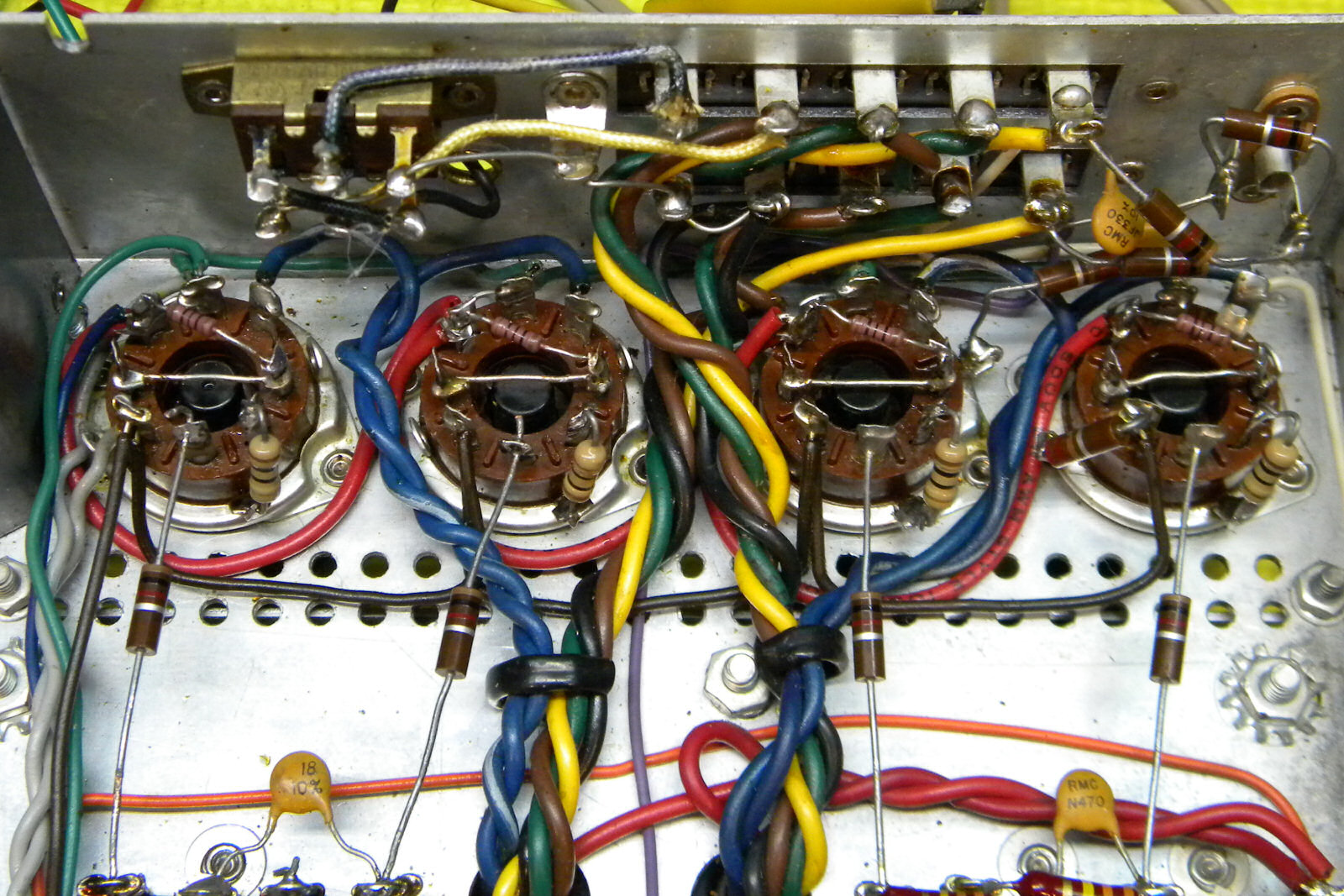
1. Coupling caps - which ones should I replace? I saw another thread that said to replace brown "dog poo" caps. There's darker brown caps in the preamp, and lighter brown ones going to the output tubes. Which should be replaced? One of the ones going to the power tubes was previously changed, so I'll be changing all 4 to match.

2. The restore kit for the fisher 400 added an in inrush thermistor in series with the power input, should I add one for this unit? If so can someone suggest a part #? I didn't record the part the last kit came with.

3. I'm adding the adjustable bias as well. I had this thread on that mod for the 400
https://www.audiokarma.org/forums/index.php?threads/fisher-400-adjustable-bias-mod.961754/
I think I've done it right but can't quite remember how I did it last time.

I did a successful power/sound check today after I'd replaced the main caps with the Hayseed Hamfest kit, and redid the bias circuit with the silicon rectifier. First try, no mistakes, no smoke! (I highly recommend Hayseed Hamfest, their caps are the only way I'll do this)

A three prong cord will be added as well.
Have I missed anything important?
 

Attachments

  • IMG_1902.JPG
    IMG_1902.JPG
    189.3 KB · Views: 76
  • IMG_1905.JPG
    IMG_1905.JPG
    131.3 KB · Views: 73
  • IMG_1907.JPG
    IMG_1907.JPG
    165.6 KB · Views: 71
Register to hide this ad
Fisher sometimes used film caps in the coupling cap positions. If they are film caps and they test ok it is usually ok to leave them. Show us some pics of the coupling caps. The community will provide some feedback on their thoughts.

I would opt for a CL-80 or CL-90 thermistor but that's just me.

Adjustable bias is a good idea, but even more important are adding screen resistors and cathode current measurement resistors.

I don't try to put 3 prong cords in. You need to find out how the chassis is grounded before you do. Some Fishers have funny grounding setups and you could do more harm than good. Others will be along to comment on that.
 
Oh yeah. The 500B has a selenium rectifier for the heater supply circuit. You may want to replace that with a modern rectifier. Note that you may have to add a resistor in series as the selenium rectifiers had higher internal resistance. Just dropping in a silicon rectifier may make the heater voltages go too high without the added resistance.

I'm in the middle of refurb'ing a 500B with Hayseed caps. I'm slow rolling it right now as I'm just very busy in work and life. I haven't got too far in the project yet, but have a thread that I update when I make progress.
 
You might want to ask to move this thread to the Fisher area. You'll get more expert help there.
 
"If they are film caps and they test ok it is usually ok to leave them."

Film caps fail with age, and you can't predict when it will happen. Replacing the coupling caps is part of routine maintenance in units this old, particularly if you're charging a customer for the work.

Jack
 
Adjustable bias is a good idea, but even more important are adding screen resistors and cathode current measurement resistors.

I don't try to put 3 prong cords in. You need to find out how the chassis is grounded before you do. Some Fishers have funny grounding setups and you could do more harm than good. Others will be along to comment on that.
10ohm cathode resistors are being added. Where do the screen resistors go and what value should I use?

Now that this is in the fisher forum I'm wondering what people will say about adding a 3 prong cord.
 
Screen resistors should be carbon comp and should be soldered right up against the screen pin. Typical values are 470 ohms to 1K (not overly critical). I don't always use them, but I keep the leads to the screens short, and I test carefully with equipment capable of observing frequencies out to at least 100 MHz. I do always install control grid stoppers, 1k to 1.5K carbon comp. Regardless of what people say, stereo components aren't 100% safe unless there's a 3-wire cord.

Jack
 
I've only seen 100 ohm resistors for screen grid stopper resistors but that might be my inexperience.
 
I've only seen 100 ohm resistors for screen grid stopper resistors but that might be my inexperience.

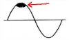
100 ohms is common in pseudo-triode mode, but otherwise, the values are varied. I often wonder how many of the classic vintage amps without screen stoppers might exhibit intermittent HF oscillations that weren't ever detected by the manufacturer. I've seen parasitic oscillation in RF power amplifiers from the '50s and '60s that I'm certain the designers weren't aware of. It wasn't so easy back then to detect a small 80 MHz oscillation riding on a portion of a much larger modulated sine wave.

parasitic.jpg

Jack
 
The screen grid bleed resistors are also a good idea, along with cathode protection.

Fisher500-BScreenGridCathodeMods.jpg
 
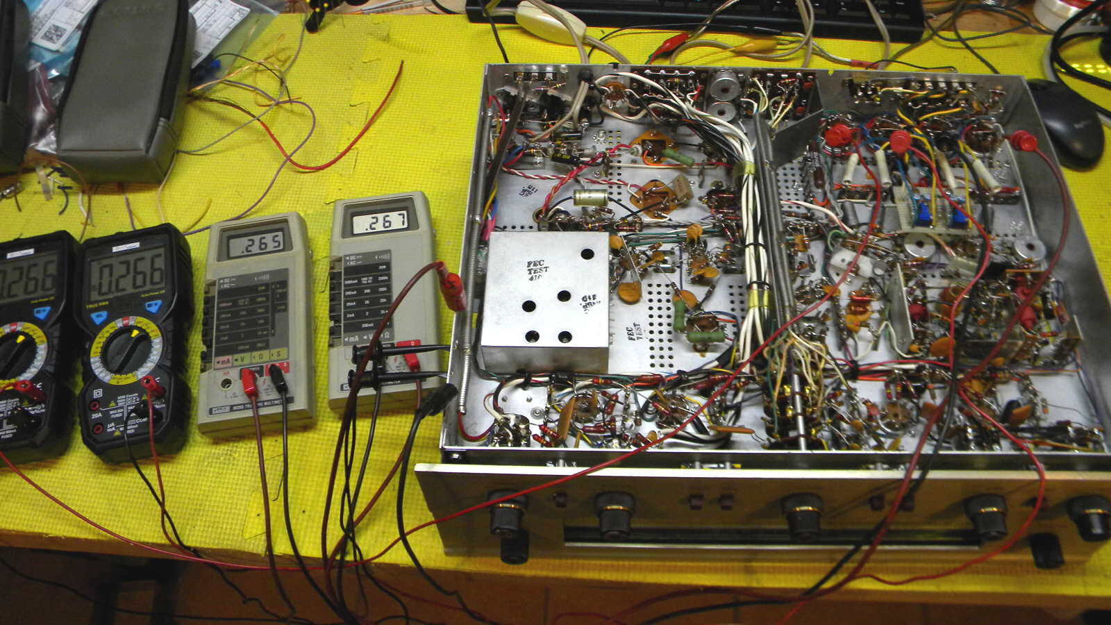
470Ω resistors as previously suggested are probably just fine. I used 100Ω/½W resistors and it worked out very well. With the Siemens rectifier replaced and dropping resistor sized to get the proper voltage, the outputs' bias currents were easily adjustable to really good values:

Fisher500BBiasSetting.jpg


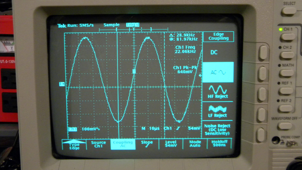
Some purists would say that the bias might be too low and allow crossover distortion, but the 'scope doesn't lie. No base-line lag and none of that peak wave silliness (oscillation) even at 22KHz:

Fisher500B-22KHzWaveR.jpg
 
Metal film and carbon film resistors both use a spiral-wound deposition, so they're inductive. Not saying this will create a problem in this particular receiver, only that it defeats the purpose of the stopper.

Jack
 
What is that small, periodic signal on the main waveform (and which point in the amp are you observing)? Would also be interested in knowing the BW of the scope and probes (I assume the latter are set to 10:1).

Jack

Jack
 
An AK article on the topic of 3-prong improvements.

https://audiokarma.org/forums/index...wer-cord-when-restoring-old-tube-gear.757446/

Main issue for most vintage units is possible ground loops.

I do also know that for some Fisher units (not the 500B) you need to be mindful that if it has certain center channel wiring that the chassis might not actually be at true ground potential. Thus using a 3-prong cord could introduce different problems. I believe the Fisher KX-200 and KX-100 are some that have this configuration.
 
The use of screen stopper resistors is always a part of best design practice, not always required in every case, and mandatory in others to prevent parasitic oscillations from forming. In this case however, the screen stopper resistors are not being added to address garden variety parasitic oscillations, as Fisher receivers were never plagued with such problems.

Today they are added to pentode and UL output stages to break up what amounts to a tank circuit that can form in certain designs of these types when an otherwise very low impedance path exists between the screen grid of an output tube, and modern low ESR power supply capacitors used in restoring vintage equipment -- a problem made all the worse if power supply capacitance is increased in an effort to improve dynamic performance. Installation of screen stopper resistors for this purpose -- renamed as Screen Stability resistors since they were never present in the original design -- damps out a destructive form of transient instability that can develop, that left unchecked can result in a violent discharge (an arc) within a power tube between the screen grid, and the cathode. This was a huge problem 40 years ago when the restoration of vintage equipment first picked up steam, and folks were taking a queue from a young upstart company (ARC) that was really making waves in vacuum tube audio design at the time by (in part) employing power supply designs that used (by comparison) massive amounts of power supply capacitance. Experimenters would then add additional PS capacitance to such designs as the Dynaco MK III, Eico HF-60, or Heath AA-40, only to be plagued by sporadic output tube arcing. But even when originally specified values for the power supply caps were used, the arcing continued.

The arcing was first blamed on the use of poorly produced modern manufactured tubes that were first appearing at the time, and in some cases, that was true. But when NOS examples exhibited the same behavior, the modern tubes were off the hook. While today resolving the problem is easy, back in that day, there were two huge hindrances to resolving this issue:

1. To this day, I have found nothing even remotely addressing the concerns of output tube arcing in any of the vintage electronic bibles, or even current day publications. Therefore, there was nothing to go on regarding the issue, as it was a new phenomenon happening in equipment that had never displayed that conduct before.

2. There was no Internet 40 years ago, so there was no ability to consult/communicate with others regarding the issue.

Over the course of about 10 years of working on the issue in my spare time (throughout the 80s), I finally determined the source of the arc events: Tubes that had arced were broken open, with all showing significant damage to the screen grid, and usually a puncture hole in the cathode. From that then, I developed the simple solution of adding Screen Stability resistors where no screen stoppers previously existed, which completely resolved the issue. The thinking up to that time had not considered that it was a screen grid event. It was a few years later when the internet became available and sites like AK sprung up that I became aware of just how many others (world wide) were experiencing the problem with no resolve as well. I'd answer whenever I saw the issue pop up, and the response was always definitive that it resolved the issue. It wasn't until AudioXpress contacted me (16 years ago now) to pen an article on the issue however that my solution developed a more widespread awareness. Even today however, I'm surprised at how many techs -- new and old -- still don't include them in their restorations. They are cheap insurance, and stop any circuit induced tendencies that promote output tube arcing cold.

There are four factors that contribute to the need for Screen Stability resistor installation. The design of Fisher receivers includes two of the factors (use of fixed bias and high Gm tubes), and as such, typically ran without issue during their original service period. But when modern PS caps are installed during restoration work, their installation should be considered mandatory. For the purposes of this discussion, the use of 0.25 watt 100Ω resistors carbon film resistors serve perfectly for the need, easily allowing full sustained power output to be produced, yet also providing a secondary benefit of fusing action should a tube go south on its own. Larger value resistors have never been found necessary in any case, and only act to waste power output if used.

Dave
 
Back
Top Bottom