
• The move to the new server is done. There are some software and database maintenance updates in process. This has us passing the hat around to help out. We appreciate any donations. Seriously, even a dollar helps. The payment page may be found here - https://www.audiokarma.org/support.html

Fisher 500c burned resistors

scombridae

New Member
Hello everyone,

I recently recapped my Fisher 500c with the metalbone kit. I put it on the Variac and fired it up on the first try. I was amazed it went so effortlessly. My worst fears became reality when after 45min of playing at moderate levels brought snapping electrical smoking nastiness to my life. Let me first say I am not super knowledgeable but I can make up for it in effort and a eagerness to learn. Looks like this amp is going to be a great opportunity.

Long story short V10 output got super hot and smoked. Upon further inspection, terminals 2 and 3 got hot enough to melt the insulation from the wires. I also noticed two resistors I believe to be R120 and R85 on the schematic fried. Additionally, the unit had a 4amp fuse instead of the 3.2amp recommended.

I have since replaced with the correct fuse, cleaned up the wiring and replaced the burnt resistors. I then slowly powered up the amp again but the two resistors started smoking again at 80-100v.

Do I have a bad transformer/s? Do I have a short? Where should start to look and test? How do I test for a bad transformer? How do I test to see if my tubes are still good?

Thanks in advance for any help
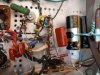
 

Attachments

  • PB260007_lr.jpg
    PB260007_lr.jpg
    92 KB · Views: 191
  • PB260008_lr.jpg
    PB260008_lr.jpg
    84.5 KB · Views: 170
Register to hide this ad
Hi, and Welcome! To be sure, you need to get access to a tube tester, but its very possible the one tube is shorted.

You could remove the two tubes from the good working side, and put them in the smoking side and watch the resistors with your variac. A volt/ohm meter will be your best friend here!

If the one tube is shorted, don't switch it to other sockets as it will fry the resistors on those sockets.
 
I bet that output tube is dead shorted. But regardless get the problem fixed or the output transformer could be next.
 
I had a shorted 6BM8 on a Monacor amp and it was doing almost the same: It was working for a few seconds before some resistors smokes.

I've replaced the tubes and the resistors and all is fine...

My 2 cents.
 
Well my good friends. Thank you all for your quick replies. I put the supposed (good tubes on the the A side of the output and hoped that it would be this simple. Unfortunately, the two resistors started to smell very quickly so I shut it back down. It hasn't happened too much but I'm beginning to enjoy the smell of burnt electronics. I'm afraid of putting new tubes in the amp and frying them with bad transformers, if that is possible. Does this mean I have a bad transformer/s? How do I go about checking this without blowing myself up? I have a pretty nice Fluke ready to go to work. The resistors that are frying are the ones on the main power transformer. The tubesocket that took a beating is the A or right output transformer. Thanks again everyone.:tears:
 
scombridae,
if you look at the power supply part of the schematic, it shows some anticipated voltages for different voltage rails emerging from different parts of the power supply and powering different sections of the receiver.
i suggest turning on the receiver via the variac to about 60 volts. With the receiver upside down, check the voltage on those voltage rails I mentioned earlier. They won't run as high as they would at 120 volts, but they should proportionally be similar. If one of those voltage rails is way off, track down the problem on that one voltage rail.
 
Audiodon is right, it's time for some troubleshooting. As noted, the most logical first step is to start checking voltages. Unfortunately, before you get to that point things start melting. As suggested, you can start ramping up the line voltage with a variac, and only go partway up. The difficulty is trying to determine a "pre-smoke" voltage so you can start checking things. That's tough to do. Plus, the resistors are damaged.

As Craig suggested, V10 might have been shorted. Since you swapped output tubes and the problem stayed in the same place, that's not it.

First things first. Did it work before you put in the metalbone kit? If so, the most likely problem is a wiring error.

Since the problem is only on one tube for that channel, it's not likely the problem is the output transformer. Unless you've got heat damage on pin 3 wiring for V11 and you just haven't noticed it yet.

R85 and R120 terminate the filament string to ground. Pin 2 on V10 is one end of the tube's filament. That's a clue. There is way too much current going through the filament string. That means there is a chance that something is wrong with the filament connections (pins 2 & 7) on V10.

Double check all of your wiring that connects to V10. Make sure the 10 ohm cathode resistor is wired to the correct pins.

Triple check everything you touched. And, replace those resistors.
 
Thank you both audiodon and fisherdude for your help. I will do all the above and check my wiring three times, which is going to take some time. Doing some snooping around the bad resistors I noticed one is grounded to a post that also has R149 (820k) going to the fuse. R149 is reading 1000k. Is that way out of range and could this be a problem?
 
Both R85 and R120 are grounded at one end. R149 is also grounded at one end. If they use the same ground point that's fine.

R149 is listed at 820k. It's a 10% tolerance, that would be a max of 902k, so it's not that far off. Higher value resistors tend to drift upward over time. Replace it if you wish, but this isn't the reason those resistors are failing.
 
Okay I got everything wired correctly. I fired it up and now I have no sound. My voltage readings seem a little high on the output tubes. Pin 6 is reading -20v on all tubes. Pin 3 is reading around 447v. Pin 5 is all over the place from 110mV to 230mV. Is this normal? I know Pin 6 is supposed to be closer to -17v. I'm going to play with changing R132 to get this down.

The other issue is two wires (grey and white) coming from the main power transformer are dead, no voltage. I did some googling and someone suggested these are for filament power for the outputs and are supposed to register 6v. Is this true? these are the two wires that were connected to R85 and R120.
 
That 6V will be AC are you measuring it as AC? Do any of the lights turn on? If they do the same 6.3 VAC is powering them.
 
Ok here are the measurements for the main power transformer
green 0v
yellow 6.6v
grey 3.2v
white 3.2v
black (going to fuse) 14.4v
black 101v
red 169v
red 2.6v (ground of c98)
orange 13.6v (rectifier)
brown 13.8v (rectifier)
Does it look like anything is off here?
 
Um, sumpin don't look right. You'e not measuring each of those wires to ground (chassis) are ya?

I am not familiar with that amp, but I would assume the two black wires are the 120 volt in to the power transformer so they should be reading 120 volts.

If its using the 5AR4 rectifier tube, and if the orange and brown wires are the heater wires, they should be 5 volts, and the two red rectifier wires should be something like 700 or 800 volts.
 
Last edited:
I have high voltage on the output transformers 447w to pin 3 of the four 7391 tube sockets. Are you saying that my main transformer should also be giving more voltage? Does this mean I need to locate a another main power transformer?
 
Hello fisherdude. I do have a schematic for the 500c, though I admit it's a little confusing. I'm confused as to what voltage is coming from which transformers. Anyway, I'm out of town and will be back on wednesday. I'm really determined to try and fix this unit. It was given to me as a non working unit and I'm trying to restore and get it to work. I really appreciate your help. Thanks
 
It looks as if you referenced ground to the chassis on the leads. ALL Leads off the transformer are AC and get referenced to the other lead in the circuit. Once it goes thru a rectifier, then it becomes DC.

Look at the schematic. Find the power transformer. Look at the transformer coils on the schematic and locate the actual wires for each of the 4 pairs of leads. 2 will be heater/lighting circuits, 1 will be the BIAS Circuit, and the other is highvoltage circuit to run everything else. Set your meter to AC and with power on check each pair of leads for voltages.

We need a picture of the underside of the unit itself and closeups of the POWER SUPPLY AREA and the output area.

Larry
 
Hi larryderouin,

I'm out of town until wed. the 8th. I will shoot a photo of the underside of the unit when I get back and take some new readings off the wires. Thank you for your help. I really appreciate it.
 
One step closer

So now I have what seems like correct voltage coming out of the Power transformer. Here are the findings.

Blk pair 117v
Red pair 170v
Brn/Org pair 24v
Grey/Wht pair 6.5v
Grn/ Yel pair 6.6v

I actually have sound but it is low (lower than speaking level) and super distorted. I'm getting sound from both channels and all the tubes are lit up. Where should I look next?
 

Attachments

  • IMG_0155.jpg
    IMG_0155.jpg
    80.6 KB · Views: 71
Is the low sound in both channels? It sounds like a power supply issue but you really need a schematic to take voltage measurements and pinpoint the offending culprit.

Post the schematic if you can. The only transformer that should have voltage coming out of it, is the power transformer. The two output transformers have (high impedance) voltage going into them, and small voltages (low impedance) 4Ω and 8Ω coming out.
 
Last edited:
Back
Top Bottom