

Kelly Moore
New Member
Hello AK’ers,
I purchased a 500C in decent condition. It is my first Fisher and I’m super excited to restore it.
I initially brought it up on my variac and got absolutely nothing. The current was reasonable.
I bought a restoration kit from Hifi Audio. It’s been convenient to have all the parts and nice step-by-step directions.
When I got to replacing the bridge and 1000uf caps, I traced the destination and found something confusing.
This is the circuit:
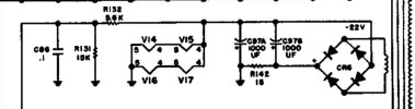
I started tracing down the V15 and V14 line and found the wire at V14 pin 4 grounded.

This would ground the heater voltage on V15. I don’t think the tube would pass any signal without the heater.
It looks like it hasn’t been touched and like this came from the factory. I’m not sure how this could’ve been possible.
V15 is the L-R high filter amp.
If I clip the wire short, it fixes the problem but swaps position of V14 and V15 on the schematic. But this is weird.
I looked out online for some hi-rez photos of the area to see if this was normal. One I saw kinda looked the same as mine and another looked like the white wire on V15 pin 5 was moved to pin 4 which would deliver voltage to V15.
What do you all think? Do any if you have pictures of this area on your 500C’s?
Thanks for your input,
Kelly
I purchased a 500C in decent condition. It is my first Fisher and I’m super excited to restore it.
I initially brought it up on my variac and got absolutely nothing. The current was reasonable.
I bought a restoration kit from Hifi Audio. It’s been convenient to have all the parts and nice step-by-step directions.
When I got to replacing the bridge and 1000uf caps, I traced the destination and found something confusing.
This is the circuit:
I started tracing down the V15 and V14 line and found the wire at V14 pin 4 grounded.
This would ground the heater voltage on V15. I don’t think the tube would pass any signal without the heater.
It looks like it hasn’t been touched and like this came from the factory. I’m not sure how this could’ve been possible.
V15 is the L-R high filter amp.
If I clip the wire short, it fixes the problem but swaps position of V14 and V15 on the schematic. But this is weird.
I looked out online for some hi-rez photos of the area to see if this was normal. One I saw kinda looked the same as mine and another looked like the white wire on V15 pin 5 was moved to pin 4 which would deliver voltage to V15.
What do you all think? Do any if you have pictures of this area on your 500C’s?
Thanks for your input,
Kelly


