• The move to the new server is done. There are some software and database maintenance updates in process. This has us passing the hat around to help out. We appreciate any donations. Seriously, even a dollar helps. The payment page may be found here - https://www.audiokarma.org/support.html

Fisher 500c Tubes to Improve Sound

HEADPHONES are tapped off the speaker leads, before the speaker screw boards, with resistors inline to drop the power so the headphones can handle the power. 330ohm 1w dropping resistors at the headphone jack. One thing to check with headphones is balance. Turn balance all the way to right or left. If the sound follows to the same side, you're ok. If the sound tracks to the other side, no problem. Just reverse the resistors on the leads at the jack. How many ohms are the drivers on the Grado's. I find that a low impedance driver on my 400 and 800c tend to break up and distort faster and easier than a high impedance headphone. My son bought me a pair of Dr. Dre's for Xmas. What a friggin waste of materials on their part and $$ on his part. I played them for about an hours then sent them back. Brought out my old reliables. I have a pair of PRO-4A's I bought as high school freshman in 1969 (260ohm), a pair of Koss SP/3X cups (the frames broke up about 5 years ago) that I bought in 1974in the Navy, that I modded into a pair David Clark Military Ear Protector headset cups, and a New pair of Pro-4AA (260ohm). All 3 handle everything without problem.

So check the channel orientation and then clean the contacts in the jack with DeOxit and Q-tips. As it's an open design you can clean it after soldering, before closing it up. And check the value with a meter of the 1w 330ohm resistors. They are 10%, but I'd replace them if they are 5% or more high or low

Thanks, belatedly for this excellent post.

The Grado's are 40 ohms impedance.
 
If your phones are a low impedance type, then simply use lower value dropping resistors to compensate for the lower impedance of the phones. Something around 100 Ohms at 1W may be more appropriate.

Dave
Dave, My Grado's are 40 ohm impedance.
 
HEADPHONES are tapped off the speaker leads, before the speaker screw boards, with resistors inline to drop the power so the headphones can handle the power. 330ohm 1w dropping resistors at the headphone jack. One thing to check with headphones is balance. Turn balance all the way to right or left. If the sound follows to the same side, you're ok. If the sound tracks to the other side, no problem. Just reverse the resistors on the leads at the jack.

So check the channel orientation and then clean the contacts in the jack with DeOxit and Q-tips. As it's an open design you can clean it after soldering, before closing it

I just picked up a 500c. I’ll post up later but my headphones are reversed. If I am following this correctly, do I open it up from the bottom and find the leads to the headphone Jack? Swap the left and right by unsolder and resolder?

Is it common for them to be reversed?

Lastly, I have all USA made 12ax7 tubes except the ones under the shields. V16 &v17 are made in Russia. Mullard I believe but now they are put back. Does it make any difference or should I look for some USA made 12ax7? I only noticed the tape head input was noisy when I checked noise level with no input just volume set up about 1/2 way.

Thanks in advance,

DR
 
The headphone access is behind the SPEAKER SELECTOR switch. Open the box by CAREFULLY jiggling the box to free it from the 3 tabs that hold it onto the chassis. There are 2 resistors for the L and R headphone channels. Just swap the resistors. Yes, it is common that they are reversed.

As for the tubes, if you're happy with the sound, don't do anything. If not, you can play the tube swapping game, but it can get costly and it's trial and error to find the tubes that make the sound you want.

The noisy tape input can be a multitude of issues. Wait for others to chime in on that one. It will help to describe exactly what the noise is and how you have everything connected to generate the noise and what are all the knob settings.
 
Last edited:
03240CCD-00B6-47D2-8277-C3DD29E37D40.jpeg
The headphone access is behind the SPEAKER SELECTOR switch. Open the box by CAREFULLY jiggling the box to free it from the 3 tabs that hold it onto the chassis. There are 2 resistors for the L and R headphone channels. Just swap the resistors. Yes, it is common that on they are reversed.

As for the tubes, if you're happy with the sound, don't do anything. If not, you can play the tube swapping game, but it can get costly and it's trial and error to find the tubes that make the sound you want.

The noisy tape input can be a multitude of issues. Wait for others to chime in on that one. It will help to describe exactly what the noise is and how you have everything connected to generate the noise and what are all the knob settings.

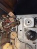
I have opened up the and see two resistors, two wires off of the resistors, blue and red wire, and two rectangular idk what they are resistors? Is it possible just to swap the red and blue (UofA colors for this Wildcat!) wires to swap headphone output?

If I don’t have to flip it over and trace it out I would be happy. Going to post up my endeavors on the Fisher thread.

Thanks for the help so far.
 
It's the two cylindrical resistors that you swap. I'm sorry - you don't swap the resistors. That makes no sense. You swap the wires going to the resistors.
 
It's the two cylindrical resistors that you swap. I'm sorry - you don't swap the resistors. That makes no sense. You swap the wires going to the resistors.

I was hoping that the wires were on the output side of the resistors , going to the headphones (earphones) jack. Makes it easier to do. Thank you!!
 
You should be able to swap wires at the headphone jack. The diagrams shown in Fisher manuals showing the tip as right channel were correct for the time but sometime in the '70s or '80s, the standard was reversed to have tip as the left channel. I have searched unsuccessfully for a published standard for several years.

Note also that 3.5 mm to dual RCA cables can have either orientation on the 3.5 mm and need to be tested for continuity. I usually mark the plug with red or white tape indicating which RCA connects to tip.
 
It's the two cylindrical resistors that you swap. I'm sorry - you don't swap the resistors. That makes no sense. You swap the wires going to the resistors.

I made the swap (red and blue leads) and it works correctly now! Thank you guys for your help!

I have opened it up and it has been gone through already for the needed repairs to protect it.

Note to those who have to do this, the metal housing shield that covers the back of the speaker selection control is held in place by short spring steel legs, by friction. (It was removed prior to the photo shown just in case you are looking for it, it’s not there in photo sorry )

They just simply compress a little bit and pop in or out. Two at the bottom corners and just one at the top left side of the metal shield.

I was a bit scared to try and remove it but if you pop the top left off by pushing back slightly towards the rear of the receiver and then lifting the whole metal shielding straight up it will pop off quite easily.

It is a little bit scary working on something so old and delicate. At least to me.

Will post up on a separate thread here w Fisher 500c in title.
 

Attachments

  • FA5DCC0D-425F-42AE-AA05-A0ADA2C3188E.jpeg
    FA5DCC0D-425F-42AE-AA05-A0ADA2C3188E.jpeg
    102.8 KB · Views: 6
Last edited:
Back
Top Bottom