• The move to the new server is done. There are some software and database maintenance updates in process. This has us passing the hat around to help out. We appreciate any donations. Seriously, even a dollar helps. The payment page may be found here - https://www.audiokarma.org/support.html

Fisher 500TX rebuild

AK577

Active Member
Hello

I am in the process of rebuilding the power supply board along with the others. This is my first actual project.

I bought this receiver couple years ago and it never worked correctly. The last three weeks I’ve been researching everything and I attempted to fix it. I found a shorted output transistor and two bad resistors. I replaced those and it actually started working for the most part.

It had distortion when turned up, and my scope indicates it only has around 30 watts rms before clipping. This was at 1kHz, one channel driven at a time. Both acted the same way.

I bought a kit on eBay that I know I overpaid for, but it supposedly has all the capacitors that need to be changed along with instructions. I’ve removed the power supply board this morning to replace the capacitors and found something that isn’t factory and I have no idea what to do.

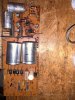
Something is soldered to one of the transistors Q972 I believe. It connects to one of the pins and goes back to ground.

I am not sure what to do, I tested the transistor and it tests okay. Any help would be greatly appreciated!!!
 

Attachments

  • 330D974B-FFE0-4F11-9DEA-39EC351BF516.jpeg
    330D974B-FFE0-4F11-9DEA-39EC351BF516.jpeg
    133.7 KB · Views: 54
Register to hide this ad
That's a ceramic disc bypass cap. Can you see the value on it? Find it on the schematic?
 
The schematic shows a 0.01uF C978 bypass cap from the emitter of Q972 to ground through terminal 9E. The board seems discolored in this area, making one wonder if there's been some kind of damage that would have required C978 to be replaced by a prior owner/tech, but with a 0.02uF unit. How do the traces look under the board? Any damage that might have caused someone to replace the cap 'outboard' by connecting directly to the transistor socket? Can you otherwise find C978 elsewhere? I'm not seeing it in the pic, but the field of view is small.
 
The schematic shows a 0.01uF C978 bypass cap from the emitter of Q972 to ground through terminal 9E. The board seems discolored in this area, making one wonder if there's been some kind of damage that would have required C978 to be replaced by a prior owner/tech, but with a 0.02uF unit. How do the traces look under the board? Any damage that might have caused someone to replace the cap 'outboard' by connecting directly to the transistor socket? Can you otherwise find C978 elsewhere? I'm not seeing it in the pic, but the field of view is small.

I found C978 near those bottom two silver capacitors. I took a picture of the board top and bottom.

The previous tech broke the board near the mounting screw in the middle.
 

Attachments

  • 5386369E-8EC7-4A60-81DF-881740ACAC1E.jpeg
    5386369E-8EC7-4A60-81DF-881740ACAC1E.jpeg
    178.2 KB · Views: 36
  • 06640E49-751E-424B-8D63-C9CF434E2EA0.jpeg
    06640E49-751E-424B-8D63-C9CF434E2EA0.jpeg
    160.5 KB · Views: 35
Shape a piece off a 2"x2" perf board (see Yellow shape on pic.) to bridge the gap and epoxy it in (on the bottom side). The end pin at the gap looks to be ok. Trace the board traceback to the other side and check continuity between the 2 pins. If necessary, bridge between the two pins with a piece of 20ga wire. I'll see if I can get to my 500-TX in the shed in the next couple days.
 
Pin seems to be okay, I’m at a stopping point right now anyway. The kit from eBay sucks. Gave me 1000 uf and 2200 uf instead of 100 and 200.
 
Update:

All the parts I ordered came in today, one capacitor was too long and didn’t fit…I tested the original Fisher capacitor and it showed to be in spec.

I had another 500tx I recently bought that didn’t work, I bought it with the intention of using some of the internals such as the power supply board. This one is not broken, and does not have an added capacitor to that transistor.

replaced 9 capacitors, and checked all the resistors. Wired it back into the chassis and fired it up. WORKS!!!

The bass distortion is completely gone, both channels sound great. One driver transistor on the amp board was running hot before, now it’s not!

I will be removing the amp board tonight to recap, several of the Mallory caps I removed from the power supply board were out of spec, so I know the other boards will benefit as well.

It has certainly been a learning experience, I cannot thank this site enough for the amount of knowledge it offers. More updates to come!7FC6B992-23B1-4913-A0A7-433D42F79129.jpeg
 
Nice work! That new PS board looks a lot less distressed than the prior one.

When I restored my 700T, about 1/2 of all the electrolytics (large and small) were leaking and outright bad, so I replaced them all with similar good results. Before that, I got distortion, drop outs, etc etc. I don't often shotgun anything, but in this case it was justified. Works great and sounds great now. Good continued luck with your 500TX.
 
Nice work! That new PS board looks a lot less distressed than the prior one.

When I restored my 700T, about 1/2 of all the electrolytics (large and small) were leaking and outright bad, so I replaced them all with similar good results. Before that, I got distortion, drop outs, etc etc. I don't often shotgun anything, but in this case it was justified. Works great and sounds great now. Good continued luck with your 500TX.

My luck ran out last night. I pulled the Amp board out to recap it, that all went perfect. I go to install the board and as I’m tilting it into place, something arcs. I had it plugged in to my dim bulb tester with the outlet switch OFF along with the receiver switch OFF. I unplugged it and continued the install.

Turned it on and the right channel is out. Choppy sounding, distorted. Looking around I noticed the red wire going to Q810 output transistor was disconnected. Appeared to have burnt off. I soldered it back on with the same results.

I pulled Q806 and it was dead. I swapped in another good one from my other 500tx, I have sound on that channel now but it sounds bad. I pulled Q806 again to test it for fun, and it only has one voltage on it now instead of two.

Also, I got up this morning to work on it, it has been unplugged all night. I pulled the rear output transistor out to test it, it sparked…….. I assume it’s the power supply capacitors keeping current on everything or possibly the work of a higher being trolling me.

The output transistors tested okay. I assume they’re fine. Again, I really do not know what I’m doing. Larry has helped me out so much though, I cannot thank him enough.
 
Sounds like those big power supply caps were still partially charged. Best to discharge through a resistor to chassis ground before beginning work. That one has caught many of us!
 
1KΩ 5W works for me.
@Dave451 Would you know of any non-nte transistor subs for FISHER's? TR1032-5(NTE129), TR1033-5(NTE128), TR1034-3(NTE159), TR1035-5 (nte81)

Just for ease of ordering and a bit of overkill, if the output's do crap on ya, get some MJ21193G and MJ21194G.
 
Just for ease of ordering and a bit of overkill, if the output's do crap on ya, get some MJ21193G and MJ21194G.

I ordered the 95 and 96 transistors, they were out of the 93 and 94. I have not installed them yet, glad I didn’t. They weren’t the cheapest, I don’t want to fry them too with these shenanigans.
 
These are the transistors on the board on my 500-TX. ALL MOTOROLA!
Q801/802 01051-7
Q803/804 02052-7
Q805/806 01062-7......EDIT 1-10-2023....SK Type 3124/289
Q807-808 02062-7.......EDIT 1-10-2023....SK Type 3114/290

01059-7 and 02059-7 are motorola #'s for the outputs.
 
Last edited:
Larry,
On transistor subs, sorry but no I don't. All were good in my 700T and I'd hit the "all transistors" website if I need to sub/replace. Evidently, there are folks who don't favor using NTE subs, but I have used them successfully in other stereo and ham radio gear. Just takes looking carefully at the datasheets in the context of the circuit being served.
Dave
 
MJ21193 - MJ21194 are almost exactly the same as MJ21195 - MJ21196. Difficult to find any meaningful differences on the data sheets. Use whichever you can find. Both are way ahead of the older MJ15xxx series, which were also very good.
 
I’m still trying to fix this amp board. I have found Q806 to be faulty. It does not have voltage on the emitter with the multimeter test. I do not have anymore of these TR1033-5 transistors to swap in. I cannot find a replacement online. I’d like to find another TR 1033 so I can still use the cool looking heat sinks.

The only other problem I’ve found is CR802 is open and two other diodes on the left channel allow current to flow in either direction. The left channel sounds good though. I have some diodes on order to replace them all.

If anyone can tell me which transistors to get, I’d greatly appreciate it. This stuff is so confusing.
 
See post 13 above for NTE cross fit's. They're the only game in town for old stuff, unless you strip the amp board of the parts 500-TX and swap around.
 
They’ll be here Tuesday. Would it be safe to install the new output transistors as well or keep using the old ones until I know everything else works?

I would hate to fry these new ones, they weren’t as cheap
 
Back
Top Bottom