• The move to the new server is done. There are some software and database maintenance updates in process. This has us passing the hat around to help out. We appreciate any donations. Seriously, even a dollar helps. The payment page may be found here - https://www.audiokarma.org/support.html

Fisher 70A design vs Fisher 30A design

AnyDayNow

New Member
I’m trying to learn how my Fisher 70A tube amp works, and I chosen to work through the excellent ‘Elmer education’ offered recently by Mark on the Blueglow Electronics YouTube channel in which he walks through a Fisher 30A amplifier. I believe the Fisher 30A (1959-) is an example of a ‘Williamson’ type of tube amplifier; I’m not sure if the Fisher 70A (1954-) is or not. What I do know is, that while the 30A has only a single stage of amplification; the 70A has two stages of amplification.

They also have different output tubes. The 30A uses EL84 tubes; the 70A used 5881 tubes.

I’m just having trouble analyzing the Driver stage in the 70A amp design; the 30A amp has no driver stage.

I’m hoping a member familiar with Fisher amps, and tube amp design generally, can point me in the right direction for further study.

For the curious, the 30A uses a single 12AX7 for both the AF Amp and Phase Splitter functions and then straight into the EL84 output tubes.

The 70A uses a 12AT7 to serve the same functions, but the takes both out-of-phase signals from plate and cathode into the grids of a 12AU7 before sending opposing signals of the plate and cathode into the grids of the 5881 output tubes.

Since the gain of the 12AT7 in the older 70A amp is not as great as the gain of the 12AX7 in the newer 30A amp design, I figure some sort of amplification is taking place; but what is the 12AU7 contributing? Does the 5881 tube require a driver stage?
Enquiring minds want to know.

Also, can anyone confirm that the 70A still a Williamson design, or is it some other type?

Note: I can attach schematics of both units if rules permit (I believe they’re both in the public domain.)
 
Register to hide this ad
I’m trying to learn how my Fisher 70A tube amp works, and I chosen to work through the excellent ‘Elmer education’ offered recently by Mark on the Blueglow Electronics YouTube channel in which he walks through a Fisher 30A amplifier. I believe the Fisher 30A (1959-) is an example of a ‘Williamson’ type of tube amplifier; I’m not sure if the Fisher 70A (1954-) is or not. What I do know is, that while the 30A has only a single stage of amplification; the 70A has two stages of amplification.

They also have different output tubes. The 30A uses EL84 tubes; the 70A used 5881 tubes.

I’m just having trouble analyzing the Driver stage in the 70A amp design; the 30A amp has no driver stage.

I’m hoping a member familiar with Fisher amps, and tube amp design generally, can point me in the right direction for further study.

For the curious, the 30A uses a single 12AX7 for both the AF Amp and Phase Splitter functions and then straight into the EL84 output tubes.

The 70A uses a 12AT7 to serve the same functions, but the takes both out-of-phase signals from plate and cathode into the grids of a 12AU7 before sending opposing signals of the plate and cathode into the grids of the 5881 output tubes.

Since the gain of the 12AT7 in the older 70A amp is not as great as the gain of the 12AX7 in the newer 30A amp design, I figure some sort of amplification is taking place; but what is the 12AU7 contributing? Does the 5881 tube require a driver stage?
Enquiring minds want to know.

Also, can anyone confirm that the 70A still a Williamson design, or is it some other type?

Note: I can attach schematics of both units if rules permit (I believe they’re both in the public dating the sc
 
I suppose you might consider a 30A a Williamson-ish but its missing the second voltage amp stage thats a hallmark of the traditional Williamson design. Same first voltage amp and phase splitter setup though. The output tubes in the 30A have enough gain that an extra voltage amp stage simply isn't needed.

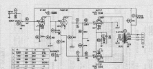
30A schematic for reference.
1789356158090.png

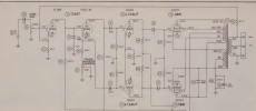
The 70A though is an honest to goodness Williamson design, though using slightly different than typical tubes.

1789355951884.png

Traditional Williamson uses medium mu tubes throughout, so all 12AU7. This uses a 12AT7 which will give more gain up front. Design is otherwise very much a Williamson though, direct coupled voltage amp to split load inverter, cap coupling to a second voltage amp stage, more cap coupling to the output. This one has a cathode feedback winding where the original Williamson doesn't, but still very much the overall topology.

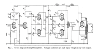
and of course the OG Williamson from 1947

1789356273605.png
 
The 70A/70-A-2/70-AZ are an ultralinear design with the addition of a cathode winding. I’m not aware of anything else quite like them. Their descendants, the 80AZ and 100, use an overall similar circuit up to the OPT, which is a much more conventional design than the 70 series.
 
yeah UL and cathode feedback are an unusual combo for sure. Honestly don't see a ton of cathode feedback amps but I don't think I'm aware of any others that do both.

currently listening to a pentode amp with cathode feedback. Completely different front end arrangement though.
 
They’re very nice sounding amps, and considering that they were Fisher’s “budget” alternative to the 50 series from January 54 to October 55, that OPT had to have been an expensive little bugger to produce. At one point I had kind of a running guess on production of the three variants based on the serial numbers, it was somewhere between 16,000 and 20,000 total, at most.
 
The EL84s in the 30A are only going to need +/-10v for full power. The ECC83 would have a gain of around 64x in that circuit where only 10-15x would be needed. Lots of room for negative feedback.
Most of us are used to seeing that circuit arrangement with a pentode first stage like in the HH Scott 222B-D series.
 
yeah two voltage gain stages for an EL84 would be significant overkill even if you used something like a 12au7 in both spots.
 
Thanks to everyone who responded so quickly to my question, and I see from his posts that Mr. Sam Cogley has experience with restoring a 70A and a 70A-2 (a version of which I was not aware). Mine are both 70AZ versions. The only difference between the 70A and 70AZ that I can see is all the switching and potentiometers (local and remote) associated with the ‘Z’ control. I’m assuming the amps will work wothout the control plugged in, and reports are that it sounds better without it.

Regarding the Williamson design, I appreciate someone posting it here. I now have a much better idea of what constitutes a Williamson design. It’s just as well, I prefer the ultra linear sound, anyway.

So, to my question concerning the role of the driver stage, I take it the while the EL84s in the Fisher 30A don’t require all that much voltage at their input, the 5881s do. Further, since neither the 12AT7 nor the 12AU7 have as much gain as the 12AX7, the additional stage of voltage gain is required to drive the 5881s. I’ll reread the circuit descriptions offered above as I continue my ‘Elmer-entry Education’ on the Blueglow Electronics YouTube channel.

Again, I appreciate the response and hope to have these two amps up and running soon, well, actually they were both received in working condition, but I want to be sure they’re operating up-to-spec before I put them into service.

Edit: Special thanks to Gadget73 for schematics and detailed discussion.
 
Last edited:
70A:
12AT7 with a gain of: 31.78 (30.04dB)
12AU7 phase inverter with a gain of ~0.9
12AU7 with a gain of: 7.89 (17.94dB)
those are unloaded numbers from HERE. So, almost 48 dB of gain through the preamp.

1v peak input to 35v peak input needs ~30.9dB, which is going to leave ~17dB of negative feedback or less, depending on sensitivity. Maybe 11dB of NFB for a 500mv peak signal. Have to remember the Ultralinear setup puts quite a bit of NFB into the power stage as well.

The second layer of coupling capacitors in this arrangement can make it tricky to get the NFB loop to be stable and makes transformer quality much more critical than what the 30a's arrangement would need. Or they can roll off problem frequencies so they're not a problem anymore.

Makes me wonder if some Carver 275 tricks can be used to roll off the NFB in the treble and end up with a flatter response. I'm too tired to brain on that one right now. :whip:
 
Thanks to everyone who responded so quickly to my question, and I see from his posts that Mr. Sam Cogley has experience with restoring a 70A and a 70A-2 (a version of which I was not aware). Mine are both 70AZ versions. The only difference between the 70A and 70AZ that I can see is all the switching and potentiometers (local and remote) associated with the ‘Z’ control. I’m assuming the amps will work wothout the control plugged in, and reports are that it sounds better without it.

Regarding the Williamson design, I appreciate someone posting it here. I now have a much better idea of what constitutes a Williamson design. It’s just as well, I prefer the ultra linear sound, anyway.

So, to my question concerning the role of the driver stage, I take it the while the EL84s in the Fisher 30A don’t require all that much voltage at their input, the 5881s do. Further, since neither the 12AT7 nor the 12AU7 have as much gain as the 12AX7, the additional stage of voltage gain is required to drive the 5881s. I’ll reread the circuit descriptions offered above as I continue my ‘Elmer-entry Education’ on the Blueglow Electronics YouTube channel.

Again, I appreciate the response and hope to have these two amps up and running soon, well, actually they were both received in working condition, but I want to be sure they’re operating up-to-spec before I put them into service.

Edit: Special thanks to Gadget73 for schematics and detailed discussion.
The A-2 was an oddball, only available for two months between the original aluminum chassis 70A and the 70AZ, from what I can tell. It’s a 70A in the 70AZ chassis. I’ve seen a handful pop up for sale over the past 15 years.

The second month the A-2 was listed for sale was the first month the Z-Matic retrofit kit was available.

70A:
12AT7 with a gain of: 31.78 (30.04dB)
12AU7 phase inverter with a gain of ~0.9
12AU7 with a gain of: 7.89 (17.94dB)
those are unloaded numbers from HERE. So, almost 48 dB of gain through the preamp.

1v peak input to 35v peak input needs ~30.9dB, which is going to leave ~17dB of negative feedback or less, depending on sensitivity. Maybe 11dB of NFB for a 500mv peak signal. Have to remember the Ultralinear setup puts quite a bit of NFB into the power stage as well.

The second layer of coupling capacitors in this arrangement can make it tricky to get the NFB loop to be stable and makes transformer quality much more critical than what the 30a's arrangement would need. Or they can roll off problem frequencies so they're not a problem anymore.

Makes me wonder if some Carver 275 tricks can be used to roll off the NFB in the treble and end up with a flatter response. I'm too tired to brain on that one right now. :whip:
Don’t forget the odd cathode feedback winding in there, too, though I have no idea what impact it has on gain.
 
The A-2 was an oddball, only available for two months between the original aluminum chassis 70A and the 70AZ, from what I can tell. It’s a 70A in the 70AZ chassis. I’ve seen a handful pop up for sale over the past 15 years.

The second month the A-2 was listed for sale was the first month the Z-Matic retrofit kit was available.


Don’t forget the odd cathode feedback winding in there, too, though I have no idea what impact it has on gain.
It's another form of direct feedback in the transformer. Does about the same thing as ultralinear taps but is much more critical about winding symmetry. Maybe a higher NFB ratio than Ultralinear.
 
DirtyErnie: Thank you so much for posting the gains of both voltage gain stages. I’ll check the link tomorrow, but please note in your labels that the phase inversion takes place in the 2nd triode of the 12AT7; the 12AU7, as I read it, has both triodes dedicated to AF amplification.

Also, when you cite to the ‘ultralinear taps’, are you referring to the screens being fed (on Red-Green and Orange wires from a Red ‘center tap’ coming from the 440v power supply? I can clearly see the cathodes of the 5881 tube winding their way through the output transformer on Green-Yellow and Green through the White ‘center tap’ through the RC network to ground which looks very familiar from having studied the path of current from the output tube’s cathodes on the Fisher 30A amp. The downside, for me, is that, with the cathode windings, it’s no longer possible to install separate RC networks to help balance tubes that aren’t part of a matched pair.

I’ve attached, if I’m successful, a Sam’s Photofacts which curiously does not include the voltages from the different stages of the power supply. So I’ll give them here, from the Fisher schematic: directly from the rectifier tube 5V4G you should see 445 Volts, after R15 (at the powe supply), you should see 440 Volts on the Red wire into the output transformer as mentioned above, after R16 you should see 385 Volts toward the plates of the driver tube 12AU7 (knocked down to 190 Volts at each plate), and finally 360 Volts toward the plates of the AF amplifier and phase inverter of the 12AT7. The 360 Volts gets knocked down to 90 Volts by R4 (220K) for the first triode, and to 220 Volts by R7 (100K).Sams70A_Schematics.JPEG

ZacktheDog: I’m hoping the 70A’s will be worth holding on to as well. The 80AZ has some user friendly touches and looks good outside a console; the 70AZ was what I could find when I was looking.
 
Yes, Ultralinear taps are the screen grid taps on the transformer. Typically '43%' for the 5881/6L6 family of tubes. With the cathode feedback, it might be 33% on the screens, 10% on the cathodes.
 
DirtyErnie: Thanks for the very helpful link

Sam Cogley: Great information on the different 70A versions. I didn’t realize that Fisher made some with aluminum chassis.
 
DirtyErnie: Thank you so much for posting the gains of both voltage gain stages. I’ll check the link tomorrow, but please note in your labels that the phase inversion takes place in the 2nd triode of the 12AT7; the 12AU7, as I read it, has both triodes dedicated to AF amplification.

Also, when you cite to the ‘ultralinear taps’, are you referring to the screens being fed (on Red-Green and Orange wires from a Red ‘center tap’ coming from the 440v power supply? I can clearly see the cathodes of the 5881 tube winding their way through the output transformer on Green-Yellow and Green through the White ‘center tap’ through the RC network to ground which looks very familiar from having studied the path of current from the output tube’s cathodes on the Fisher 30A amp. The downside, for me, is that, with the cathode windings, it’s no longer possible to install separate RC networks to help balance tubes that aren’t part of a matched pair.

I’ve attached, if I’m successful, a Sam’s Photofacts which curiously does not include the voltages from the different stages of the power supply. So I’ll give them here, from the Fisher schematic: directly from the rectifier tube 5V4G you should see 445 Volts, after R15 (at the powe supply), you should see 440 Volts on the Red wire into the output transformer as mentioned above, after R16 you should see 385 Volts toward the plates of the driver tube 12AU7 (knocked down to 190 Volts at each plate), and finally 360 Volts toward the plates of the AF amplifier and phase inverter of the 12AT7. The 360 Volts gets knocked down to 90 Volts by R4 (220K) for the first triode, and to 220 Volts by R7 (100K).View attachment 3836952

ZacktheDog: I’m hoping the 70A’s will be worth holding on to as well. The 80AZ has some user friendly touches and looks good outside a console; the 70AZ was what I could find when I was looking.
Do you have the Z-Matic controls for your 70AZ amps? They often get separated over the years. If they’re missing, I’d recommend retrofitting the feedback circuit to the fixed damping design used in the 70A and 70-A-2. I created several threads about 15 years ago when I was working through the rebuild of my pair that may be helpful as a guide, they’ve got some good advice from dcgillespie on upgrades and proper tuning, and a few quirks we found in the schematics.

DirtyErnie: Thanks for the very helpful link

Sam Cogley: Great information on the different 70A versions. I didn’t realize that Fisher made some with aluminum chassis.
I have no idea why Fisher changed the form factor mid-stream on the 70 series. The early version sort of resembles a baby Fairchild monoblock in design and materials. The wider chassis is nicer to work inside and makes for better wire routing, but in the end, it’s mostly cosmetic.
 
Back
Top Bottom