I have a nicely working fisher 70rt but I’m concerned about the selenium rectifier overheating. It plays fine so don’t want to mess with it if I don’t have to. I’ve replaced a selenium rectifier in a Dumont am fm tabletop radio with great success. However looking at the diagram for the fisher - it is a little perplexing. Not the same as the dumont. How would I replace this using a diode? Do I need 4 diodes or am I reading this diagram all wrong?


You are using an out of date browser. It may not display this or other websites correctly.
You should upgrade or use an alternative browser.
You should upgrade or use an alternative browser.
Fisher 70rt Tuner Preamp Selenium Rectifier

Register to hide this ad
Yes, 4 diodes or a packaged bridge rectifier. The latter would have four terminals and one mounting hole, easier to install. And you would likely have to increase R82 to make up for its lower voltage drop.
I’m looking at bridge rectifiers on mouser. Not sure how .024ADC translates. Thanks for your help.
I’m not usually a huge fan of loudness but I really like the loudness setting on this device.
Attachments


.024 amps Direct Current. Find a Bridge rectifier rated for 400volts AC and 2 Amps.
This one will do fine. https://www.mouser.com/ProductDetail/Vishay-Semiconductors/VS-2KBP04?qs=sGAEpiMZZMtQ8nqTKtFS/ERhNCRzfcON5sjErUmz0Sw=
JB-Weld it to the side or bottom of the chassis close to the original and transfer the ~(AC)leads, then the +(Pos DC) and the -(Neg DC) leads. Put heatshrink tubing on the joints so if they should get close or touch, they are insulated from each other and nearby parts, or the chassis.
R82 will probably need to be increased as Tom said. Try 27 to 30 ohms 1st. This range has been usual for my Fishers, but may need some slight adjustment for the 70-RT. Before replacing the rectifier, write down the voltages on both sides of R82. Replace the rectifier and take another set of voltage readings. Use ohms law to figure out the new resistor value.
This one will do fine. https://www.mouser.com/ProductDetail/Vishay-Semiconductors/VS-2KBP04?qs=sGAEpiMZZMtQ8nqTKtFS/ERhNCRzfcON5sjErUmz0Sw=
JB-Weld it to the side or bottom of the chassis close to the original and transfer the ~(AC)leads, then the +(Pos DC) and the -(Neg DC) leads. Put heatshrink tubing on the joints so if they should get close or touch, they are insulated from each other and nearby parts, or the chassis.
R82 will probably need to be increased as Tom said. Try 27 to 30 ohms 1st. This range has been usual for my Fishers, but may need some slight adjustment for the 70-RT. Before replacing the rectifier, write down the voltages on both sides of R82. Replace the rectifier and take another set of voltage readings. Use ohms law to figure out the new resistor value.
Last edited:
Sounds easy enough. I’m going to have to study this some before I jump in though and I very much appreciate the help..024 amps Direct Current. Find a Bridge rectifier rated for 400volts AC and 2 Amps.
This one will do fine. https://www.mouser.com/ProductDetail/Vishay-Semiconductors/VS-2KBP04?qs=sGAEpiMZZMtQ8nqTKtFS/ERhNCRzfcON5sjErUmz0Sw=
JB-Weld it to the side or bottom of the chassis close to the original and transfer the ~(AC)leads, then the +(Pos DC) and the -(Neg DC) leads. Put heatshrink tubing on the joints so if they should get close or touch, they are insulated from each other and nearby parts, or the chassis.
R82 will probably need to be increased as Tom said. Try 27 to 30 ohms 1st. This range has been usual for my Fishers, but may need some slight adjustment for the 70-RT. Before replacing the rectifier, write down the voltages on both sides of R82. Replace the rectifier and take another set of voltage readings. Use ohms law to figure out the new resistor value.
I can see neg dc goes to ground and pos dc goes to C2. Is there any particular order for the white/brown? Also, excuse my ignorance but, wouldn’t I want to leave R82 alone and instead put a new resistor between the new M1 and C2A? It might be clearer if I was at home looking at the actual device and not just the diagram.
Thanks!

That'll work too, though you'll find Ohms law doesn't work, as the waveform here is pulsed DC and not filtered as it is later in the circuit. Try 10 Ohms, increase if needed. PM me an address and I'll send a small bridge rectifier for the postage - I have a bag of them.
PioneerPro
Active Member
I have one of these and a few months ago everything was working well. The green magic eye is so cool I would turn it on and show it to friends. I am only using it as a show piece sitting on a shelve, it is not even plugged in. So the Green Eye quit working, which is one of the coolest thing about this. Can anyone tell me how to test the Magic Eye Tube to see if it burned out? I am not an expert at this and have only basic equipment.
Attachments
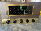
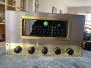
Many tube testers can test its functionality.I have one of these and a few months ago everything was working well. The green magic eye is so cool I would turn it on and show it to friends. I am only using it as a show piece sitting on a shelve, it is not even plugged in. So the Green Eye quit working, which is one of the coolest thing about this. Can anyone tell me how to test the Magic Eye Tube to see if it burned out? I am not an expert at this and have only basic equipment.
PioneerPro
Active Member
Dude, Seriously??? If I had a tube tester or access to a tube tester I would not be asking.Many tube testers can test its functionality.
There has to be a way to test a tube with a multimeter or something?
You asked and I answered.Dude, Seriously??? If I had a tube tester or access to a tube tester I would not be asking.
There has to be a way to test a tube with a multimeter or something?

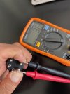
only thing you can possibly do is check across the fat pins for resistance. Thats the heater. Unless thats open, there is something else wrong. Pretty rare for tubes to just up and die totally without any warning unless it happens to be an open heater, and honestly heaters don't go bad that often.
PioneerPro
Active Member
PioneerPro
Active Member
Just for the hell of it I plugged it into a Dim Bulb Testers and sure enough it light up.
Thank You
Thank You
Last edited:
PioneerPro
Active Member
CAN ANYONE TAKE A GUESS AT THIS?
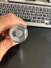
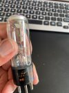
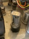
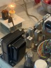
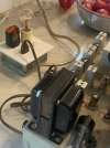
I only use this for display purposes but when I want to show it I want the Magic Eye to work and it was working just fine last year. I plugged the tuner into a Dim Bulb Tester and I pulled out each tube one by one until I got the tube that maybe the issue. Ironically it was the large main tube so I am thinking that means nothing. All the other small tubes made no difference at all and the large main tube gets warm and I tested it and I think the test said it was good. Once again I just want the Green Magic Eye to work.
I only use this for display purposes but when I want to show it I want the Magic Eye to work and it was working just fine last year. I plugged the tuner into a Dim Bulb Tester and I pulled out each tube one by one until I got the tube that maybe the issue. Ironically it was the large main tube so I am thinking that means nothing. All the other small tubes made no difference at all and the large main tube gets warm and I tested it and I think the test said it was good. Once again I just want the Green Magic Eye to work.
Attachments
again
You're looking at the rectifier tube, it supplies all of the high voltage. Pulling it should make the tester dim, but its not probably telling you much here. If the DBT isn't at full bright, there isn't a dead short. If it was full bright and removing the rectifier dropped it, then the short is in the high voltage circuitry. Replacing that tube isn't going to fix anything, if there is a short somewhere in the high voltage circuitry, the only thing to do is find and fix it.
Honestly if you aren't using it, and especially if it hasn't been serviced, I'd park it until it can be gone through properly.
You're looking at the rectifier tube, it supplies all of the high voltage. Pulling it should make the tester dim, but its not probably telling you much here. If the DBT isn't at full bright, there isn't a dead short. If it was full bright and removing the rectifier dropped it, then the short is in the high voltage circuitry. Replacing that tube isn't going to fix anything, if there is a short somewhere in the high voltage circuitry, the only thing to do is find and fix it.
PioneerPro
Active Member
Thats is kind of what I assumed. I don't really have any experience with Tube Electronics. Probably going to park it till can get it looked at.