
• The move to the new server is done. There are some software and database maintenance updates in process. This has us passing the hat around to help out. We appreciate any donations. Seriously, even a dollar helps. The payment page may be found here - https://www.audiokarma.org/support.html

Fisher 80-T DC Voltage low at both 6X4 tube rectifier and PreAmp Selenium bridge rectifier

AnyDayNow

New Member
I’m just getting started trying to revive a new-to-me Fisher 80-T Tuner / Preamp. I carefully powered it up (isolation transformer + Variac + dim bulb current limiter) giving the capacitors hours to form, and it worked —kind of. The AM seemed very noisy, the FM pulled in stations, but the meter never centered, the dual indicator was also off by more than one number, and the audio was a bit ‘edgy,’ the phono was rich, clear, but seemed to lack volume.
I checked the resistances at the tubes and didn’t find anything alarming, but I haven’t reviewed the closely. The voltages, on the other hand got my attention because many (not all) appeared to be about twenty volts low in the tuner and 30 volts or more higher in the preamp.
So, I reviewed the schematic(s) I have and decided to check things at the start of the chain, pin 7 of the 6X4 at the rectifier tube V13 (on all schematics). The transformer was putting 190 volts AC in (as it should), but I was only getting 170 volts on the output at pin 7. Likewise, at the output of the bridge rectifier in the preamp, which serves to provide current to the serially connected heaters in the two 12AX7 tubes in the preamp section is supposed to provide 25 volts to the top of the chain, had only 14 volts, where the voltage into the first half of the first 12AX7 was supposed to be 18 volts, it was 10.4; into the 2nd 12AX7, where it was supposed to be 12 volts, it was 7.2 volts, and leaving the second half of the first 12AX7 where it was supposed to be 6 volts, I found 3.7 volts.
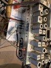
So, the first thing I did was order a new (old stock) 6X4 tube, but I’m wondering if I’m doing this correctly. Even though the unit isn’t pullling any more current than it is supposed to, should I disconnect the load from the rectifiers and retest? I don’t have a way to really test a capacitor, other than a volt meter or DMM, and I certainly don’t want to just replace EVERYTHING! (I priced all the tubes, and the sum is more than twice what I paid for the unit.) Fisher said they put top quality parts in their units, and every tech who works on them witnesses to this fact. It’s just that I’ve never worked with either rectifier tubes or selenium rectifiers before, and I’m seeking some guidance on how to proceed. Thanks in advance.IMG_2849.jpeg
 
Register to hide this ad
I forgot to mention that I found 18 VAC ripple at pin 7 output of the rectifier tube. I figured that the rectifier wasn’t working efficiently.

Edit: I also noticed on Sony6060’s post that 20 volts of ripple is not unusual with tube rectifiers. (Why don’t the posts that include your topic come up when you start a post, and only find them after you post? I guess I should spend a day searching a topic regardless before I post anything.)

Anyway, I still need help on how best to proceed, generally. I guess I’ll start looking harder at the C1/R1 side of the power supply. I would like to keep the rectifier tube in the tuner, but I may experiment with a bridge rectifier in the preamp.

Edit: I’ve ordered the capacitor leakage detector kit available from Antique Wireless Association in preparation for testing the capacitors.

Edit: And an MF470 capacitor tester for measuring capacitance and ESR.

I guess I need to start a blog or something, I would delete this thread if I knew how.
 
Last edited:
Bad filter caps will also make for low DC output, and I'd be kind of amazed if its not bad. This usually shows up as low DC and high AC ripple. High ESR, or low value both cause this. Leakage usually shows up as heat. The can itself will get warm.


The selenium usually fails with excessive voltage drop, so not real surprising there. Replacing it and adding some resistance to drop the voltage if needed is the usual course. Someone may know offhand the right value resistor but I tend to just change them, check the voltage under load, and calculate a resistor from that. That said, a bad cap at the output of the rectifier will also cause low DC voltage.

if you don't want to change everything, I'd go for new power supply caps in both the high and low voltage circuits. The rest depend on the type, many will not need to be changed and some you can't change unless you can re-align a tuner. Those types are generally of a sort that doesn't really fail anyway. Its basically just paper caps and electrolytics that give up from age, doesn't matter how good they were 60 years ago, they are just past their expiration date for reliable operation now.

I wouldn't throw any tubes at it unless you have good reason to believe they are bad.
 
Thank you Gadget73, sounds like a wise plan. I’m hoping that, by going through each circuit, starting with the power supply, the radio performance will pick up. I plan to step up to FM alignment, as I have another tuner which needs it, but there are so many ways of doing it, I have an analog scope, but I don’t have an RF sweep generator or marker. My function generator maxes out at 2 MHz.

I’ll report back when I make some progress on these power supply issues. It won’t take long for the quickie capacitor checker to get here, I’ll have to build the kit to test for leakage.

I really appreciate your taking the time to read my post and respond so quickly.

Edit: The Sam’s Photofact schematic notes a current of 320 mA at the output of the bridge in the low-voltage supply in the preamp, I should be able to use that value both for troubleshooting and calculating dropping resistor values.
 
Last edited:
the current on the DC supply should just be tube heater load but I'm not looking at exactly what they did here. 12ax7 in 12v mode is 150ma, in 6v mode its 300ma. Two parallel strings of 12v tubes would be 300ma plus whatever other load they may have tied in.

generally getting your power supply voltages right is a good first step. Might also want to clean the tube pins and sockets. I've had a lot of "dead" tuners come back to life by doing that. FM especially is crabby about bad contacts. Those brushes meant to clean between your teeth work really well for 9 pin sockets when dipped into a bit of contact cleaner.
 
I cleaned the pins after I checked the resistances and before I checked the voltages. I didn’t check the C1 can for heat, but the rectifier sure seemed to be cooking, perhaps showing the strain of excessive current draw, we’ll see. I’ll have to pick up some of those gap-tooth brushes I’ve seen XrayTonyB use.
 
Update: Capacitor C1, the first capacitor in the power supply (actually a series of four capacitors) really took a hit. The first of the four supplies the 175 VDC B+ one resistor drop down from the output of of the rectifier tube at pin 7 of V13. Rated at 40 mF, the tester quickly reported OL because it calculated the ESR as being over 100% what it should be for the standard size capacitor it thought it was. The other three capacitors in the can had great ESR reports, 1 Ohm or so, but their capacitance was often well over 20% greater than their rating.
I also tested one paper capacitor, it was rated rated at 0.47 mF, but reported 40 something nF. I’ll check the two cans in the preamp later today. They’re a lot easier to get to.

I saw where someone asked about the source of the Fisher sound. I think it is due to the fact that the techs terminated every wire by wrapping it around the post back on itself! What a pain!
 
Update: I got mixed results from the power supply caps in the preamp chassis. The high voltage can (C69 in the Sam’s Photo Facts schematic) tested OK with 40 mfd and ESR of about 1 Ohm for all three sections, just as it is rated; the low voltage can (C70 in Sam’s) tested significantly lower than its rated 1000 mfd on both sections, coming in at 54 mfd on A and 145 mfd on B; the ESR was very high, with 27 Ohms on A and 16 Ohms on B.

I tested the other three electrolytic capacitors on the Parts List, curiously used as coupling capacitors on the preamp input, recorder output, and the cathode of the 2nd 12AX7. They all failed.

Edit: I plan to test them all for leakage when I get my leakage tester built. Considering obtaining the MOSFET based adjustable voltage drop rectifier from Manuel at Electronis Old and New.

So I think I’ll stop posting to this thread. I may come back with a final report when I get the power supply back together and try the NOS rectifier tubes I ordered. But I think we can say that the low supply voltage my initial testing revealed was due to the weak power supply capacitors, not the rectifier tube or selenium rectifier (although the selenium rectifier is still suspect and I will definitely replace it).
 
Last edited:
Cap test results make sense for what you were seeing on the voltmeter. Pretty solid bet new caps will sort it out, or at least get you most of the way there.
 
Back
Top Bottom