• The move to the new server is done. There are some software and database maintenance updates in process. This has us passing the hat around to help out. We appreciate any donations. Seriously, even a dollar helps. The payment page may be found here - https://www.audiokarma.org/support.html

Fisher 800-C loud cracking in speakers randomly now dead

NorthPoleGuy

New Member
greetings!
I will start by saying I acquired a 800-C and ordered up one of metal bones kits and rebuilt the unit to the best of my ability, I also had to replace a few broken tubes. When I was done the unit powered up good and sounded great for many months, I used to to listen to music radio and input from my phone in my work shop. One day it started to make a pop sound out of the speakers randomly, usually just one and it would continue to work. One day there was a loud hiss crackling in the speakers then the unit went dark.
I was hoping that someone could point me in a direction on what to start investigating to find the cause of the failure.
thanks in advance for any pointers
Joe
 
Register to hide this ad
1st off check the FUSE in back. Replace with the SAME VALUE , 250V AGC fuse. Fuse is a 3.2A SLO-BLO. A 3.0 SLO-BLO is OK. DO NOT GO UP IN VALUE. You lose the fuse protection with a higher value.

If you have a lot of sawdust in the shop, take the 800-C outside and blow it down. Then remove each tube in turn and blow iut the socket, then reinstall the tube with DeOxit in the pins.

If you still have no power start checking the POWER SUPPLY solder connections(with the cord unplugged, use the meter in the oHms position). You could have a blown fuse, open diode, a bad can cap section, or other parts bad. If you have not replaced the CAN CAPS, it would be a good idea to do so now.
 
Thanks for the prompt replies.
My shop does not have any sawdust but a little regular dust. I keep it fairly clean so that will be first order the fuse, blow it all down then tweak and clean all tube sockets.
I have replaced all the caps in the amp with the rebuild kit. I will do a little poking around and try what you recommend Tomorrow and see what I can see. I did read how guys were cleaning their sockets and tweaking the sockets with a small screwdriver or pick to help with connections there. I will get back to you guys when I learn something, I have been reading through the forums trying to pick up some bits to use troubleshooting my 800-c. Thanks again and I will write back hopefully tomorrow.
Joe
 
Sounds just like what happened to me once: one of the EH output tubes took a hike and blew out a 10ohm cathode resistor. Scary but a pretty easy fix.

A few good up-skirt shots will help.
 
Blowing a 10ohm cathode resistor will kill the output on one side, but not the whole she-bang.

Yes, please take some "Up-the-Kilt" shots of the power supply area, and the output area. These are the most likely suspects, with the Power supply being #1.
 
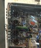
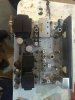
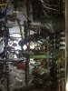
Ok so I think maybe an output tube might have shorted. The fuse was blown and there is a hot spot below one of the output tubes. All the 10 ohm resistors looked good but the larger green resistor has gotten hot. I am trying to find it on the schematics right now. I will attempt to upload a few pictures. It should be noted that my wife is the one closest to the amp when it failed and she said a little smoke came out of the amp as the fuse cleared. The only spot that shows any signs of getting hot is right next to the that large green resistor by V11
 
Last edited:
The green resistor got hot and it looks like under it got hot. I made sure nothing was touching. Shorted output tube maybe?

image.jpeg

I was incorrect I thought I changed the cans, they are still the original ones.

image.jpeg

Cleaned up nicely.
image.jpeg

image.jpeg
 
Larry: When my tube went it took out the cathode resistor AND the fuse. It was a carbon that took a few seconds to go before the main fuse went. All I could do was stand there with that "Oh, sh*t!" look on my face. That's when I switched to metals.

Speaking of cathode resistors: Those 10ohms are some big-uns North. What wattage?? Also, that big green resistor gets hot. In an over-the-top restoration it gets changed out to a 10w resistor from 7w. When it is stressed, a whitish band appears around its center. If it is blackish, then it is burning. If there was a puff of smoke, my guess would be that a resistor went somewhere.

Better/clearer/tighter shots of any area you suspect has burned will help zero in.

BTW: Mosey on over to the link below, post #19 re grid resistors. I'm not absolutely sure but it looks like you got a little more work to do:

http://www.audiokarma.org/forums/in...er-800c-to-fix-it-but-a-few-questions.443578/
 
If I had to guess, that 4-way multi-can C87 went south. I'd replace it and all the other cans for some peace of mind.
 
Ok the resistors are dale RS-5 C19201 I believe these are rated at five watts, the supplied resistors were very low wattage and a friend helped me pick out some more stout resistors.
This was my first electronics overhaul that I did, I was just amazed it worked when I was done! Got about a year of playing it before problems developed.
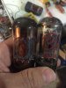
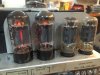
So I went and took a couple pictures then hooked up an amp meter in series and powers the amp up with no output tubes in place and it powered right up and nothing got hot. I looked the tubes over and one of them was coated pretty heavy with metal on the inside. See picture. I swapped out that tube for another spare I had and powered up the amp again and it came right up with no problems. When I get my tube tester cleaned up and working I will have to run this tube on a few tests and see what it is doing.
Not digital I started to read that link and a lot of it was over my head right now but I understood some of it. At one point I had current readings on the output tubes by measuring the voltage drop across the 10 ohm resistors and will see if I can find it in my notes.
Behamham I will have to order up some new caps to repackage the cans this winter. How do guys do these ones? Just mount new caps underneath in the chassis?
 
image.jpeg

Ok what causes the excess metal plating on the inside of the tubes? Was thinking to high of voltage on the plate? Again I am just learning so please humor my questions.

image.jpeg

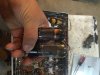
You can see the white band on the resistor like you guys mentioned. I am sure that is what got hot from the looks.

Yimage.jpeg

Think it got some of the wires hot above it.

image.jpeg
 
Ok the resistors are dale RS-5 C19201 I believe these are rated at five watts, the supplied resistors were very low wattage and a friend helped me pick out some more stout resistors....

North, those resistors are excellent, high quality resistors that would enable you to accurately measure the current draw on the individual tubes. Perfect for that purpose. However, they serve a secondary, equally important purpose: as fuses! When an individual tubes starts to draw more current as it begins to go thermal, that resistor will let go saving the transformer, if not more, from a calamitous end. The original set was low wattage for that very purpose: to fail under undue stress. Through experience I've found that 1/4 watt metal film resistors serve both functions admirably. They have extremely tight tolerance (for measurement purposes) and quickly "pop" when an over-current condition exists, (search "fusistor.") The resistors originally supplied were likely correct for your receiver.

Here is another thread that is worth looking over. It speaks to the grid resistors mentioned in the other thread quoted above. If you're using JJ power tubes, it is well worth the read and will give you much food for thought for more stable performance:

http://www.audiokarma.org/forums/index.php?threads/fisher-800c-grid-leak-resistor.269042/

And as Bruce mentioned: Think about replacing those cans as well. Whether you stuff, undermount, or replace wholesale, your receiver will be very happy you did!!

Glad you're back in business!!!!
 
Last edited:
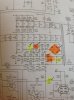
That Green resistor is R128. 1.2Kohms, 7W. We generally bump it up to a 10W unit as 1.) the 7W is now almost extinct, and 2.) the increased wattage is not going to hurt it. Ohmite makes a very nice ceramic that fits and works well.

http://www.mouser.com/ProductDetail/Ohmite/20J1K2E/?qs=sGAEpiMZZMtbXrIkmrvidMA4Up922MrgOJIOn9ABxfM=
$2.40 ea.

It's between the screen feed (C-98)and the 4 section cap (C-87D). I'd start checking the can caps for shorts, and install all of the stability mods (grid return resistors/coupling caps change; screen stability resistors; cathode resistors). Sounds like one of the C87 sections shorted and R128 took all of the load which was more than it's rated for.

The Metal plating on the top of the tubes is whats know as getter flash. Getter is a mixture of gas absorbing chemicals that is flashed during vacuum pumping of the tube, by way of RF Induction. The material heats up and liquifies, and attaches to the glass giving a chrome look to it. Over time (usually decades) the getter diminishes due to gas infiltration thru the envelope, which is absorbed into the getter. If the tube has a catastrophic failure (vacuum loss) the getter turns WHITE. Some getters are darker than others, or cover more of the envelope, due to tube type. This is not an indicator of tube health (other than the white color). The getter on yours looks good.
 
Larry,
Thanks for the detailed feedback! I was searching the schematics over for that darn resistor, thanks for putting a number on it!
Do you guys mind all the pictures I post?
I will change out those cathode resistors back to the smaller rated ones, I guess that would help protect my output transformers if another tube shorts. So what I got out of reading the links is that the JJ tubes can't handle the current flow that the circuitry in the fisher can drive? Maybe the bias circuit is out of whack a bit? So if the tube shorted internally and the cathode resistor was to big to clear that is a direct short and more than likely the output transformer could be damaged prior to the fuse clearing?
I did hook up a meter in series with the stock fuse holder to measure current using some jumpers and automotive short finder (just allows the use of a fuse holder in series with the meter) upon powering up the amp it seems to power up ok with all the output tubes removed it looks like close to 1/2 amp inrush then drops to almost nothing. So I replaced all the tubes and replaced the one that was discolored badly and same results, powered up and inrush current drops right off and seems to be ok.

So those JJ tubes seem to glow a fair amount brighter than the Old stock. Per the reading on the link you provided it looks like circuit for the JJ tubes can be tuned down a bit to prevent this? Could you explain this a bit to me?
This could explain why I have lost two JJ tubes and none of the original old stock RCA tubes?
I think I will go take some readings across those 10 ohm resistors and report back.


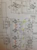
So does the C2 line between R123 and R128 go to the C1 line on the next drawing just to the left of V11?

image.jpeg

image.jpeg


Thanks a million for the feedback.
 
Yep. C1 and C2 go together.

NONE of the current production tubes can handle the overloaded voltages, resistances, etc. that the manufacturers built into the receivers of the day. Original production tubes when new could handle it for about a year, but then output tubes went for a dollar to $3.00 each. Todays tubes are about 80% of the originals with regard to grid resistance, etc. They don't like overloaded circuits, etc. JJ's are the worst! They had and still have problems with their 7591 tubes in orders of magnitude the EH and TungSol put together don't have.

Let me give you some light reading and the why's and wherefore's of increasing the reliability of 7591 and 7868 circuit's.
1st is Dave Gillespie's Article on Increasing tube life. This is the article that most of the rest is based off of.

http://www.tronola.com/html/maximize_tube_life.html

Also on the Tronola Site is a test panel of 7591 tubes done a few years ago, and it doesn't include the New Tung-Sol 7591 ReIssues. http://www.tronola.com/html/7591a_tubes.html . I would say and Dave would probably agree with most of it, that other than their "HOTTER" biasing voltage (more negative voltage for a set tube draw (ma)), The tung-Sol tubes are probably a better tube than the EH7591's.

And an explanation by Dave on the why's and wherefor's of the mods. This was taken from an earlier 400 rebuild thread, and applies to the 500 and 800 with the 7591's.

400-500C-800C MODS for BIAS and POWER SUPPLY
1.) replace the 4 coupling caps with .1uf/630V caps (OP Choice of cap)
2.) replace 330k grid resistors with 200K R 1/2Watt.
3.) install 10oHm 1/4W resistors to ground on each output tube. (*)
4.) install 100oHm 1/4W screen stabilization resistors to jumper on each tube.(*)
5.) install 10K variable resistor (pot) in BIAS POWER lead to facillitate some adjustment in the Bias circuit. (IF a IBAM OR IBBA Circuit is NOT Installed yet. Once IBAM or IBBA Installed, remove 10K pot)

See the DRAWING ON PAGE 3 of the "COMMON PARTS FOR FISHERS" Sticky thread on 1st Forum page. The pins are different for 400's than 500 & 800's due to the output tubes being different.


index.php


In THIS POST:
http://audiokarma.org/forums/index....sher-sticky-needed.327561/page-2#post-6480170

Explanation by Dave Gillespie;
If I may, here is some detail behind the recommendations for these modifications:

1. "Reducing the grid resistors to 220K": The published maximum DC resistance for grid #1 of 7591 class tubes is 300K (by RCA, Sylvania, and others). This is the maximum value allowable when the tube is operated under conditions of maximum dissipation -- which many designs nearly did -- so yes, using 330K is using a value that is right on the ragged edge.

The reason for the maximum resistance specification is to limit the value of reverse grid current voltage that can build up under conditions of maximum dissipation (read that, maximum heat). But there are other concerns that can aggravate this issue as well. Higher line voltages push the heater voltages higher, which means that today, even more heat is generated. The basic concern is that excessive heat (however it's generated) can cause cathode material to boil off and deposit itself onto the grid. This means the grid has now become a partial emitter, with any current flow it provides developing a voltage across the grid resistor that is opposite in polarity to the negative voltage applied to the bottom of the grid resistor. This negative grid current voltage then works against the negative bias voltage, causing the tube to conduct more current, generating even more heat, boiling off more cathode material, and ultimately causing thermal runaway. The production of gas comes into play with these events as well to further aggravate the issue. Therefore, to help control this condition, a maximum DC resistance is specified for the control grid to limit the amount of ill effects that can be caused by reverse grid current.

As a result, with the high temps that these units typically run at inside their cases, and importantly, because of today's higher line voltages, and because the tubes are biased "on" pretty hard to begin with, it makes very good sense to pull the value of the grid resistors back a little to help minimize the chances of developing any significant reverse grid current voltage, and the possible thermal runaway that can produce -- and this is even before the quality of modern production tubes is considered!

2. "Double the value of the coupling caps": This has nothing to do with loading on the driver stage, in fact, lowering the value of the grid resistors actually increases the load on the driver stage. The reason the cap values are increased is to keep nearly the same time constant in the RC coupling circuit between the driver stage and the output stage with the new lower value grid resistors installed.

3. "Install 10 Ohm cathode resistors": This makes for the easiest way to monitor output tube current draw, and therefore allows for the easiest way to set the bias and balance of the output stage (if such controls exist), or check to see that matched output tubes are in fact matched. These resistors are typically used for balancing currents under quiescent conditions, but can also be used to check for balance under dynamic conditions if the proper equipment is available. Balancing output tube quiescent current maximizes OPT low frequency power handling ability (by minimizing core saturation), while balancing dynamic currents minimizes overall distortion.

4. "Installing a 10K bias pot": Modern tubes are manufactured with far less precision than the best tubes from yesteryear were, and so, fixed bias amplifiers operating with tubes of modern manufacture on higher line voltages will usually need some adjustment from the original fixed setting a manufacturer provided. Installing some type of adjustable control is therefore highly desirable, and adding a DC balancing feature to that is even better. Installing these controls so that they cannot be inadvertently altered from their setting goes hand in hand with the installation of any such controls.

5. "Installing 100 ohm Screen Stability Resistors": So many folks have posted on various forums -- from all degrees of experience -- how everything is as it should be, but the output tubes will arc for no reason that they can determine. How expensive does that get when output tubes can be ruined in an instant?

Long ago, I determined that these arcs were in fact occurring from the screen grid. Many pieces of old hifi gear were designed with very little resistance in the screen circuit, which usually didn't present too many problems as the power supply caps of the day had much higher ESR values, which tended to help keep things stable. Even at that however, some designs (Eico HF-89 for example) were simply notorious for arcing output tubes because of the larger overall power supply capacitance values they employed.

Today it is all too common, with the installation of new power supply caps that have much lower ESR values, and which are so often increased in size as well (all installed on new drop in power supply boards), to have all manner of output tube arcing events occur, which leaves folks puzzled because it just never used to do that before. New manufacture tubes got the lion's share of the blame -- until even NOS tubes were arcing in these refurbished pieces of equipment as well.

With some form of transient trigger (music, an open ground, whatever), the lower ESR value caps can set up incredibly strong oscillations in what is effectively a tank circuit that's formed with the screen grid, and can cause an arc at any time. Installation of 100 ohm Screen Stability resistors (for 7591 class tubes) stops this problem virtually every time. I've never had anyone tell me that installation of these resistors did not stop the problem. Personally, I've never had an output tube arc event in nearly twenty years now, where before I had boxes of blown tubes until I could determine what the cause was, and develop an appropriate cure. In equipment such as this Fisher represents, it is very cheap insurance against such events, and produces no audible or measurable difference in performance.

Hopefully, this will help with an understanding of why these modifications can make such worthwhile improvements in so many of these wonderful instruments. With some components being virtually unobtainable now, minimizing any damaging events that might occur helps all of us to enjoy this equipment even more.

Good luck with your receiver!

Dave


PICTURES actually help us help you out with diagnostics and finding things you may have overlooked. Better 10 pair of old eye's o_Othan 1 pair of old eye's:eek:. Make sure they are well lit. Some of us are finding dark pictures hard to find on the page themselves. :confused: The more the merrier.
 
Last edited:
Larry,
Thanks for the details that helps very much. I have read it a few times and am working on fully digesting all the details. I happen to be in town and will pick up a few of the parts to start the repairs/mods.
More questions to follow, I will work on the lighting and clarity of my pictures.
 
So I stopped by our only place for any electronics parts (radio shack) and they did not have many of the parts I need to make the changes but I did find some 2.5 amp slow blow fuses.
Got home and replaced the fuse and powered up the amp. The oldest output tube is glowing brightly after a few minutes, guessing it is on its way out. I did get some voltage readings across the 10 ohm resistors. V10 1.41 volts V11 265mv both of those are the JJ tubes V13 214mv and V14 181mv. I am guessing these numbers are a bit out and the high one is getting close to failure?
I will have to order up some parts after reading the previous posts.
The good news is that it at least powers up and does not blow the fuse since changing the one output tube!
Will order up the parts for the mod and then write back to report results.
image.jpeg
 
Lowes and Home Depot both carry glass BUSS Brand fuses in the Electrical Dept.


I would seriously consider putting all of the JJ's in the CIRCULAR FILE. You've already got one redplating, and the 2nd one is getting ready to. Up to you, either a quad of old stock, or NEW Tung-Sol's or EH's, but those JJ's are only good for Target practice sooner than you think.
 
If you go back to post #13 above, within that post there is a link. Post #19 of that link explains EXACTLY what is being displayed in your last picture. Dave's explanation in post #16 above is the same: Vintage tubes can handle the current being delivered, modern tubagge can't; not without additional modification to the unit. Sure, it'll play...for a while. However, that time is limited and, as you've now experienced, it is an avoidable accident waiting to happen.

Larry provided a laundry list of modifications, one through five, that are must do's if you're hoping to bring your unit to safe/stable operation. In order of immediate importance I'd switch 4 and 5 but screen resistors must still be seen as a critical prophylactic measure against sudden tube death. This is particularly so given the cost of vintage tubes.

V-10 is toast. V-11 is untrustworthy at best. Keep them as testers only, do the mods, and once done, pick up a set of matched tubes. With a 10k pot installed, you'll be good to go for years. If you're one of those guys who become hooked on the tinkering part of this hobby, then you can move onto more refined bias controls such as the IBAM or IBBA. If not, you and your Fisher will be more than happy with the modifications already mentioned.
 
Back
Top Bottom