• The move to the new server is done. There are some software and database maintenance updates in process. This has us passing the hat around to help out. We appreciate any donations. Seriously, even a dollar helps. The payment page may be found here - https://www.audiokarma.org/support.html

Fisher 800C: Help adding 3 prong cord

mcaddie7

Active Member
Hey all,

I wanted to install a three prong power cable with a power switch installed to have save wear on the volume knob / power knob combo.

However I noticed that there are 3 wires going to / from the power switch which is different from the 2 I’m used to bypassing.

Any idea where I would hook up the ground, neutral, and hot wires from the 3 prong?

Alternatively I have a 2 prong with a switch I could use but though grounded the chassis was a good idea for safety anyways.

Any help is appreciated
IMG_7406.jpeg
IMG_7406.jpeg
 
Register to hide this ad
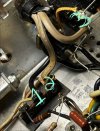
#1 wire is to the transformer primary
#2 wire is from the AC line cord
#3 is to the switched outlets on the back.

basically if you want to bypass the switch, connect all 3 together.

Or if you don't care about the switched outlets, its #1 and #2.

none of that matters for a 3 wire cord though. Hot goes to where #2 lands. Neutral goes to wherever the other wire lands. Ground goes to chassis.
 
#1 wire is to the transformer primary
#2 wire is from the AC line cord
#3 is to the switched outlets on the back.

basically if you want to bypass the switch, connect all 3 together.

Or if you don't care about the switched outlets, its #1 and #2.

none of that matters for a 3 wire cord though. Hot goes to where #2 lands. Neutral goes to wherever the other wire lands. Ground goes to chassis.
Yes my goal is to bypass the power switch all together.

I’d like to add the three prong power cord for safety reasons unless I can be convinced it doesn’t need it.

Ground to chassis, and hot goes to #2 which I guess makes sense as that is where power is initially coming in. As for neutral, would I tie 1-3 together and put neutral at that junction? It looks like 1 powered the transformer and 3 powers the circuitry nearby.

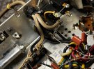
Let me know if you know more pictures
 
Put the neutral on #1 and run a jumper over to #3. That will power the amp and the outlets on the back. You may want to disconnect the leads going up to the switch.

Hot goes to the un-marked terminal where the existing power cord goes, looks like its one of the outlets on the back and jumped over to the fuse.

That will put the fuse on the hot side, and since the switch is bypassed its not going to be switching the neutral.

in stock form the fuse was on one side of the line and the switch on the other. 50/50 if you had a switched neutral or a fused neutral, just depended on which way it was plugged in.

honestly I tend to leave this sort of thing stock, often with the original cord if its still in decent shape though its probably not as safe as having a ground.
 
Your stated reason for rewiring your receiver is to save “wear and tear” on the switch. Realize, however, that the infamous switch failure with Fisher components has to do more with the electrical response to switch manipulation as opposed to a mechanical one. When you “flip” the switch, a small electrical spark is created which spark eats away at the internal elements. In simpler terms, it burns the spring until it breaks. I’m pretty confident in saying that if no power were applied, that switch would last infinitely longer.

Fisher addressed the switch failure problem by going from a 3 amp rated switch to a 5 amp one. A welcome move in the right direction but it just bought more time.

Enter the modern and simplest solution: the thermistor. It is the gateway to power, slowly permitting the ramp up of current to the switch and effectively eliminating the lighting bolts that actually do the damage. If you don’t have one installed, it is highly recommended that you do so.

If safety is a factor in deciding whether to install a 3 prong plug, that discussion has been had a good number of times. A quick search should bring those up. Here is one:

 
you can also parallel the contacts. Its a 2 section switch, half runs the reciever, half runs the outlets. If you jump across the second set of contacts, then both sets carry the load. I'd avoid using the switched outlets for anything that pulls real current if you do this.
 
Yup, that’s what’s done with the double pole switches, i.e. the original 3a switch. Makes it a more robust switch. Still, reducing the spark reduces the worry. Even better, plug into a strip or a switched bucking outlet and eliminate the possibility of sparking completely.
 
Enter the modern and simplest solution: the thermistor. It is the gateway to power, slowly permitting the ramp up of current to the switch and effectively eliminating the lighting bolts that actually do the damage. If you don’t have one installed, it is highly recommended that you do so.
Also .01/1kv ceramic disc capacitor with around a 120 ohm resistor in series wired across the power switch, if not already present, for contact arc suppression (AKA a snubber) can also go along way in preserving the switches contacts life, assuming conservative power switch current ratings were OEM chosen to begin with.

Tube amp SS rectification power supplies, especially those using voltage doubling type circuitry with their large value electrolytic capacitors are the biggest switch contact stressing offenders, where tube rectification, when used, provides a more controlled soft start with less inrush current & also tame the reverse EMP current when the power switch is opened.

I sometimes have used both (suppression & thermistor modification methods combined during rework/updating a particular integrated amp or receiver in the past, both SS & tube audio equipment.

Carry on.
 
Back
Top Bottom