• The move to the new server is done. There are some software and database maintenance updates in process. This has us passing the hat around to help out. We appreciate any donations. Seriously, even a dollar helps. The payment page may be found here - https://www.audiokarma.org/support.html

Fisher 800C Restoration Thread

mcaddie7

Active Member
Met an older gentleman who was about to toss out some old hi-fi gear. Sat and chatted with him for a while and he had some incredible stories.

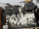
Long story short he insisted zero payment for any of the gear, so amongst other things I received a what appears to be pretty mint Fisher 800C.
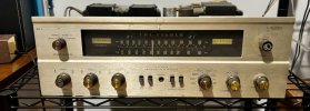
IMG_6839.jpeg
IMG_6840.jpeg

So, please don’t yell at me, but given how great of shape it was in after dusting I decided to hook it up to a varied, dim bulb, and amp meter and see if we could reform the electrolytics and get it to start back up.

I spent two days, starting at 5V and worked my way to 120v, never spiking above 0.5A, however no sound was ever had. Bummer. But from test equipment there doesn’t appear to be any shorts.

I’ll be removing all tubes, and see what I get for voltages after the rectifier.

My plans are / already ordered:
- New electrolytics
- Install new rectifier to replace selenium
- New lamps
- Do bias mod so I can use newer tubes in the future.

Anything else that is a must / cleaning tips? There’s obviously a little dust left on the thing and didn’t know if a damp toothbrush may help or if it’s better to leave the patina
 
Register to hide this ad
I absolutely LOVE the old Fisher tube gear, and will follow your thread for updates. I've restored about a half dozen of various models over the years, mostly 500C, and encountered a variety of issues. Right now I have one on the bench, and was wondering where people are going for parts these days? It' appears this unit may need a new volume pot/switch. Any resources for parts you can share would be helpful. Thanks, and best of luck with the 800C restoration!
 
Just FYI but there is a dedicated Fisher forum. You can ask a moderator to move your thread there if you choose. It’s ok in this forum but you might zero in on more Fisher folks over there. Anyway, great find. There are some great Fisher 500c and 800c restore threads, particularly the ones by Dave Gillespie. The 500c and 800c are basically the same except for the addition of the AM band on the 800c tuner.
 
So I started by buying a restoration kit (I know I know) from eBay but from my findings it seems like Tubetycoon from a certain auction site is affiliated with the original fisher company somehow and really know there stuff.

Anyway the kit was beautiful and allowed me to fix some deemphasis problems that I guess the original radio had, change out and relocate some caps that would normally get too hot, change the rectifier, as well as adjust the bias for the amp and fix that problem by swapping out a resistor value. I did all of this so far. The kit also includes all new film caps to replace all other non ceramic cap which will be this weekend’s project.

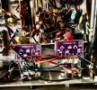
For now I’ve also replaced the tone control PEC with a board that replaces it with small discrete components. Tight fit but it looks nice and keeps original wiring. IMG_7014.jpeg

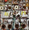
Safety resistors on output tubes (blown before tube overheats) as well as the start of cap change.
IMG_7016.jpeg

Also took apart the face plate to clean dial, glass, and knobs. Waiting for that all to dry before installing new lamps and post picture of the front and Chasis cleaned up. I’ve also ordered new power electrolytics as well that should arrive next week.
 
Update: replacing all large electrolytic caps got me to the required 430VDC with all tubes removed for CR6 and CR7 portion of the amp.

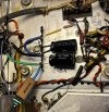
Now back to SR1. I’m beating my head against the wall. I removed everything, and confirmed that my transformer legs (orange and brown) are what they should be AC.

Next I connected them via the Rectifier and unloaded get the appropriate DC voltage across the + and - terminal.

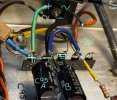
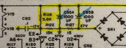
Next I rewired everything to wha I believe is correct. Yet, I get no + voltage and get a -31VDC where the red X is which I’m assuming is wrong, as the schematic shows -17 and a + voltage on C95A.

Any help or advice?IMG_7285.jpeg
IMG_7284.jpegIMG_7276.jpeg
 
Well now, the schematic is wrong. When the 4 12AX7 tubes in the phono preamp and line/tone control stages are installed, there will normally be about a 4-5 volt drop across R127, so the + terminal of the bridge will normally be about that amount above ground. If those tubes are not installed however, there will be virtually no drop across R127, so that the + lead of the bridge will basically read 0 volts to ground.

I hope this helps!

Dave
 
Hi Dave thank you for this bit. So as far as you can tell it’s wired correctly? The only other thing that concerns me is that I’m getting around -33V. Does that drop to around -17V with tubes installed or is that wrong in the schematics as well?
 
The voltage at C92 drops to -17 volts because of the voltage divider action via R119 and R122. If you're getting -33 volts directly across the output of the bridge, and the original resistor values are installed in those locations, then you will typically get about -20 to -21 vdc at the junction of those resistors. A greater negative voltage than that listed is hardly a bad thing, as, most examples (even vintage pieces) of the 7591A need more than -17 vdc for the tubes to idle at a reasonable quiescent current.

If you're getting the full bridge output of -33 volts (minus the 4.5 volt drop across R127 = -28.5 vdc) at the junction of R119 and R122, then likely R122 is missing or effectively so.

Dave
 
The voltage at C92 drops to -17 volts because of the voltage divider action via R119 and R122. If you're getting 33 volts directly across the output of the bridge, and the original resistor values are installed in those locations, then you will typically get about -20 to -21 vdc at the junction of those resistors. A greater negative voltage than that listed is hardly a bad thing, as, most examples (even vintage pieces) of the 7591A need more than -17 vdc for the tubes to idle at a reasonable quiescent current.

If you're getting the full bridge output of -33 volts (minus the 4.5 volt drop across R127 = -28.5 vdc) at the junction of R119 and R122, then likely R122 is missing or effectively so.

Dave
R119 was switched to a different value to help raise the bias, it was part of the "kit" that was installed to help restore and improve old 800Cs and their flaws. Per a previous reponse, once I installed all tubes back in (after checking for shorts and what not on my tested; took forever!), I then found that the -33V dropped to around -14 or so. I'm assuming I need to mess around with that resistor at some point to get the bias in a "happy" range.

However, with all tubes installed, my issues from before still persist. I get 0.4A current draw, a slightly lit bulb, and B+ (right after CR6) goes down to 305V which is wrong as it should be around 430V per the schematic.
View attachment 3632249

What's the best method for troubleshooting this issue now? Is it safe to remove SR1+ and - from the receiver, install all tubes and see if CR6 B+ raises? I suppose I could also remove all tubes (I get the B+ I want) and then slowly add tubes one by one and turn on for a second or two to check for voltages? Any advice on troubleshooting would be great.


Long story short: B+ good at 430 without tubes, bad at 305 with tubes. SR1 has weird voltages but is mostly fixed when tubes are installed (apparently that is okay). Let me know if anyone needs any wiring.
 
"a slightly lit bulb" If you're still operating the receiver through a DB tester, then that will cause all readings to be significantly lower than when operating straight from the power line. Things are apparently safe enough at this point to install all tubes EXCEPT all four output tubes, and then operate the unit straight from the AC power line. Let us know what voltages you are getting in that scenario.

Dave
 
"a slightly lit bulb" If you're still operating the receiver through a DB tester, then that will cause all readings to be significantly lower than when operating straight from the power line. Things are apparently safe enough at this point to install all tubes EXCEPT all four output tubes, and then operate the unit straight from the AC power line. Let us know what voltages you are getting in that scenario.

Dave
Hi Dave thank you for the help. Nothing is blowing up or heating with short 30 second turn on for measurements so that’s a good as well as below .3A current draw.

Was thinking of bottling up without a dumb bulb, I’ll take measurements for you all, then start adding one tube, turn on, measure, rinse and repeat.

Hopefully finding out which tube / socket is causing the voltage to drop that far
 
Well I feel like an idiot. Removing the DBT, I installed one tube at a time, and to my surprise was getting 435 B+ exactly as I should have been. After installing all but 2 tubes (we'll get to that) the receiver is making beautiful music!

I checked the bias and it's at -22V for the output tubes. Is this good or should I change it as I know I'll want to replace the tubes one day when they fail.

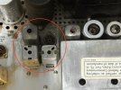
So now onto the other issue; the sparking. When installed V4, and power on the amp, I get large sparking in the area below area.
IMG_7314.jpg

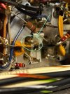
Looking on the top side it seems to be coming from one of these. Was going to make sure nothing was shorted this evening when I get home. But any tips? I don't really have much experience with (I think are variable caps).
IMG_7320 2.jpg

Sounds
 
Looks like the 2nd AM IF transformer. The terminal may be shorting to the can internally. Only way to know is to remove and disassemble it. Definitely needs to be done though to prevent the possibility of the primary coil being burned open if the terminal is the plate terminal of the transformer.

Dave
 
Its not just bent too close to the mounting clip is it? Can't really tell from the angle of the pic. If you don't care about tuner functionality I guess you could unhook the power supply to it and just leave it alone if there is some internal fault you don't want to deal with right now.

forgot these are "modern" with shared parts for AM and FM, so you can't just unhook the AM section. I guess you could unhook both sides of the AM transformers and just connect the wires together so it powers through the FM IF transformer to keep FM functionality though.

The output tube grid voltage doesn't really matter, different tubes will pull different currents at any given grid voltage. Modern tubes tend to flow more current at a given voltage than the old ones did too, sometimes by a fair amount. Really need the cathode resistors added to see what is happening.
 
Okay so I confirmed it’s this transformer.

I took the cover off and made sure all pins weren’t touching the chassis. It appears that the sparking is coming from the mica capacitor area at the bottom of it.

From research it seems this is kinda common? Can I replace just the mica, or should I replace the whole unit if I can find one.

I don’t mind repairing as I have the skills but whatever you all think is best. So close lol
 

Attachments

  • IMG_7320.jpeg
    IMG_7320.jpeg
    112.5 KB · Views: 5
Silver mica disease, fun. Gut the old cap and replace it will work. A replacement can might have the same problem so not a ton of point in finding another.

Hopefully the FM cans are good, they are subject to the same problem. It doesn't always shoot sparks out but it makes funny noises and bad performance
 
Oh golly is that hard to repair?

Any guidance would be great on how to repair it as I never learned about those older transformers in engineering school. It’s been an adventure getting this far
 
You're into the land where i know the theory but have never done it, so take this with some salt and do some looking for posts with pics

If you take the can off, down in the base you'll find fingers between the primary posts and the secondary with a wafer of mica between them. Usually the fix involves peeling back a finger and removing the wafers. A new cap of the right value gets attached to the legs underneath. Then you have to align it with a signal generator

And no i don't happen to know the value to use, but I'm sure its somewhere. Different for the 455kc AM ones and 10.7mc FM ones too.
 
You're into the land where i know the theory but have never done it, so take this with some salt and do some looking for posts with pics

If you take the can off, down in the base you'll find fingers between the primary posts and the secondary with a wafer of mica between them. Usually the fix involves peeling back a finger and removing the wafers. A new cap of the right value gets attached to the legs underneath. Then you have to align it with a signal generator

And no i don't happen to know the value to use, but I'm sure its somewhere. Different for the 455kc AM ones and 10.7mc FM ones too.
Problem 1 Remaining: Bad AM IF transformer
I've also ordered some 100pf caps to help repair that IF transformer I found out to be bad. I'll try repairing this today. Right now with the tube removed for this IF transformer, I don't get any FM reception, I'm assuming fixing this one IF transformer should restore full functionality?


Problem 2 Remaining: Bad Phono section?
When plugging my phone in via the Aux section, the receiver sounds absolutely gorgeous. When plugging my Dual into the phono low section, it sounds "okay" at best, but there is a decently loud, rhythmic humming. It's livable but given how good the amp portion sounds, it makes me think the phono section has something up. Every 30 seconds or so you get a quick hiss / louder hum that immediately goes away. Tubes tested good but could this be a bad tube, or something else in the phono section?
 
Back
Top Bottom