• The move to the new server is done. There are some software and database maintenance updates in process. This has us passing the hat around to help out. We appreciate any donations. Seriously, even a dollar helps. The payment page may be found here - https://www.audiokarma.org/support.html

Fisher 800c right channel buzz

Dan Finch

New Member
I've got a Fisher 800c that I finished a full restoration with the fisher doctor kit.

it's working pretty well, sounds great. However, it's got an annoying buzz in the left channel on all inputs, it is not present until a few seconds after turn on, when the "stereo beacon" light comes on. It does completely go away when I switch "tape monitor" on. It doesn't sound like a hum, more of a buzzing. the buzz changes slightly through adjusting bass/treble/high pass filter.

Any ideas of what to measure or try to fix to repair it?
 
Register to hide this ad
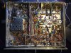
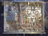
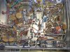
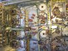
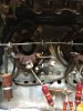
Since it goes away when the Tape Monitor switch is turned on, that means it also must go away when the volume is turned full down as well. If so, this means that the problem will be located around the section of V17 that is made up of pins 1, 2, and 3 of that tube, or the selector switch portion (and its wiring) that feeds this portion of V17. Also, make sure that the reverb jack jumpers are clean and making good contact -- but not pushed in so far as to short the jumpers to the barrel of the jacks and short out the signal. Some good underside pics of the unit are always helpful.

Dave
 
Since it goes away when the Tape Monitor switch is turned on, that means it also must go away when the volume is turned full down as well. If so, this means that the problem will be located around the section of V17 that is made up of pins 1, 2, and 3 of that tube, or the selector switch portion (and its wiring) that feeds this portion of V17. Also, make sure that the reverb jack jumpers are clean and making good contact -- but not pushed in so far as to short the jumpers to the barrel of the jacks and short out the signal. Some good underside pics of the unit are always helpful.

Dave

Yes, goes up and down with volume. just noticed that it is really bad when the ground is left off the record player. Also with record player disconnected from phono lo, the buzz is on both channels evenly. I removed and de oxited the reverb jumpers: no effect. I also swapped the tubes and deoxited the connectors between left and right (v19/18) and filters (v17/v16) no change.

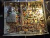
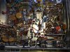
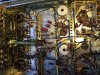
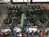
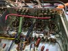
In my attached pics you'll see an ac/dc converter for front LED lamps. This doesn't affect the noise-it buzzes with this in or out of circuit. Too bad the pics are limited to 800x600. Let me know if you need something zoomed in.

image.jpeg image.jpeg image.jpeg image.jpeg
 
Last edited:
It doesn't look like any work was done with V-17 (there really isn't any components to replace with that tube), so was the noise there before the rebuild was done? Your work looks very nice!

Dave
 
Dan; I hope that 2nd picture is a camera anomaly. Looks like it went thru a car crusher.
I gamma corrected them and resized them.......
Dan 1 gamma corrected.jpg

Dan 2 gamma corrected.jpg

Dan 3 gamma corrected.jpg

Dan 4 gamma corrected.jpg
I'd ask a moderator to move the thread over to the FISHER FORUM, so you get the full treatment of mods, add-ons, etc., for the 800C. I'm still not impressed with FisherDoc's choice of electrolytics, but the films look like DME's or similar. There are additional things to be done to the output section that will increase longevity and safety of the output tubes, no matter what you put in there. In addition, an individually adjustable bias system will help to balance out the tubes for better operation and hence sound quality, plus you'll be able to adjust the Phase inverter to optimum operation with a procedure on the forum..

Dave's the best we have there on FISHER Forum, He'll get the buzz outta there.
 
It doesn't look like any work was done with V-17 (there really isn't any components to replace with that tube), so was the noise there before the rebuild was done? Your work looks very nice!
Dave
Honestly, I don't know for sure. I was scared about something blowing up since it sat for 20 years, that I dove right in and did the restoration.
I've got a nice Metcal soldering iron, so it's easy to make it look nice!

I really don't even know where to start to try and debug this. This thing is so nice, I hope I can make it quiet!

The pic is a 'panoramic' on an iphone. was hoping to get a bit more resolution, but the forum limits to 800x600 unfortunately

Thanks for your responses so far.
 
Well, so much for Apple having better idea's!(sarcasm). The phono buzz is probably separate from the original buzz. Check around V17 for broken joints, shorted together tube pins, loose wiring, solder bridges across two points, anything that you think looks out of the ordinary compared to the other side of the tube. Pins 1-2-3 are one side, 6-7-8 are the other side. 4-5-9 are the heater pins.
 
Does one of the 10 ohm resistors look burnt on one of the 7591A's. The second one from the top specifically?
 
Good catch. Looks burnt to me too.

Dan. replace the 10ohm on V13. That tube is effectively shut down and not conducting to the output transformer so you have V14 trying to compensate. Not good for V14.
 
Good catch! yeah, that's burned out.
I'll replace it and see what's going on. I did blow a fuse just yesterday. I had the buzzing before the blown resistor, so I don't think that's the root of the buzz issue (but does address some other issues I didn't even talk about!)
 
Here's the resistor zoomed in. Now why did it blow. Hmmm. Was listening pretty loudly.

But that's another thread. I'll post confirmation that the buzzing still exists with the resistor replaced.
image.jpeg
 
The resistor blew almost with certainly because there are no Screen Stability resistors installed. Circuit conditions are such that even with the original can caps still in place, oscillations can be triggered under dynamic conditions that cause the output tubes to arc, which take out a cathode resistor in short order. The installation of Screen Stability resistors prevents this from happening, and really should have been part of the original design -- but little was known of such events back in the day. Check the Fisher Forum for the how-to on Screen Stability resistors.

Dave
 
Dave, looking at the forum post for these screen stability resistors, I see how to do it.
Should I have both the resistors that connect to the bus connect to the new "AFTER" net? R123 and R128. I think so.

I'll do this today and fix the 10 ohm.

index.php
 
Should I have both the resistors that connect to the bus connect to the new "AFTER" net? R123 and R128.

Yes, the 1.2K resistors need to be moved to the new bus - "AFTER" in your diagram. These are the 7W and 1W resistors that are part of the power supply.
 
The resistor blew almost with certainly because there are no Screen Stability resistors installed. Circuit conditions are such that even with the original can caps still in place, oscillations can be triggered under dynamic conditions that cause the output tubes to arc, which take out a cathode resistor in short order. The installation of Screen Stability resistors prevents this from happening, and really should have been part of the original design -- but little was known of such events back in the day. Check the Fisher Forum for the how-to on Screen Stability resistors.

Dave

Screen stability resistors installed. Replaced 10 ohm. Much better! Noise still there but muted a lot.
image.jpeg image.jpeg
 
With only one output tube operating, there was no common mode power supply noise rejection taking place, so 120 Hz hum was elevated. Replacing the resistor then allowed for a more balanced current flow through the OPT, allowing it to cancel out most of the power supply noise, making for less noise in the output.

Dave
 
Have you checked the tube draw across the resistor. Ideally should be about 320 to 360mv, to get you in the 75%-80% range of tube.dissipation. But even with ideal conditions I've blown a few of them for no apparent reason.

Did you ground the heater circuit resistors separately when you added the 10 ohm resistors? These are grounded to pin 5 on one of each pair of output tubes normally. But when you add the 10 ohm resistor, it elevates the heater circuit and can cause a hum. R101 - R106 220ohm 1/2w. Looks like you might have but I can't be certain from the pics.
 
Once a tube arcs, it is forever prone to arc again, even if all the safety measures have been taken.

Dave
 
Have you checked the tube draw across the resistor. Ideally should be about 320 to 360mv, to get you in the 75%-80% range of tube.dissipation. But even with ideal conditions I've blown a few of them for no apparent reason.

Did you ground the heater circuit resistors separately when you added the 10 ohm resistors? These are grounded to pin 5 on one of each pair of output tubes normally. But when you add the 10 ohm resistor, it elevates the heater circuit and can cause a hum. R101 - R106 220ohm 1/2w. Looks like you might have but I can't be certain from the pics.

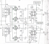
Larry, are you sure on the reference designators? R101-R106 are like 1.5M and 2.7M on my schematic (800c)
Screen Shot 2016-04-23 at 8.42.47 AM.png
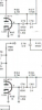
I don't see a 220 ohm resistor anywhere in the circuit drawing around the power tubes:
Screen Shot 2016-04-23 at 8.32.34 AM.png

I think you may mean that I should have the following:
1.) Grid return resistors = 200K vs. original of 330K (I don't - still 330K, will change)
2.) Coupling caps = .1uf vs. 0.047uf (I don't, still 0.47uF, will Change)
3.) 10 ohm cathode resistors on pin 5 of each output tube to ground. (done)
4.) 100 ohm screen resistors to pin 4-8 of each output tube from screen buss. (done)

Though I don't see what you mean about grounding the heater circuit. Those ground through a capacitor (C14/C15) and also C92 from the common net.
 
Last edited:
Back
Top Bottom