• The move to the new server is done. There are some software and database maintenance updates in process. This has us passing the hat around to help out. We appreciate any donations. Seriously, even a dollar helps. The payment page may be found here - https://www.audiokarma.org/support.html

Fisher 95 schematic or suggestions to reduce DC offset

rickl

I'm just a bass player
Subscriber
I’m looking my my neighbor’s 1966 Fisher 95 (serial #52826). This is an all in one unit with a solid state receiver and a built-in turntable on top. AUX Hi/low inputs, Record, and speaker RCA outputs.

I’m looking for a schematic for an 85 or 95 or something made around 1966.

She bought this new in 1966. She needed help hooking up the speakers (she thinks her son cut the RCA connectors off the speaker wire sometime when he was younger).

She didn’t know how to connect the speakers (Fisher Model 10). I didn’t fully understand the problem (with my wife interjecting help…) so I offered to take the unit home and look at it.

I replaced the death cap /resistor pair with a xy safety cap. This fixed the mild shock I was getting when I touched the hot chassis. I didn’t try to reverse the non-polarized plug since I didn’t think an 80-year-old woman would know this.

I cleaned the pots with Deoxit, oiled the pot shafts so I can turn them and built some speaker wires (RCA on one end/spade terminals on the other end). I also cleaned and added a drop of turntable oil to the Garrard turntable spindle. And replaced the burned-out bulbs.

Does anyone have an 85/95 schematic or know of a similar 1966 built Fisher that I can look at? Outputs are TR110 in Quasi-complementary.

There is about 100mV of DC offset that I’d like to reduce. Since this is cap coupled, I'm using a 8 ohm resistor load for each speaker output.

I’m able to inject a sine wave in the AUX hi input and get a nice signal out so I know the amp is working. I’d like to reduce the DC. Here is a pic of the amp chassis.
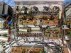
chassis.jpg

here is the amp board from volume pot
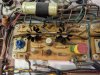
amp-board.jpg

the lower right corner in the 'IN' from the volume pot.

I’m tempted to just return it since I wasn’t expecting to ‘restore’ the amp, but it is a nice unit.

Thanks
 
Last edited:
Register to hide this ad
while digging around on hifi engine, i came across a 105 stereo receiver from 1966. here is a screenshot of the output board. It looks very similar to the amp board pic above.
upload_2021-8-30_12-0-37.png

I'll review others but I think I might have found a schematic of something similar.

I checked the output caps and the 105 schematic doesn't list the capacitance and (what I think are the) output caps are not stamped with the values.

I can measure them with my cheap transistor tester and might do that.
 
If its cap coupled, there isn't anything for offset. The cap is leaky and needs to be replaced.
 
The cap is leaky and needs to be replaced.

Thanks. This is my conclusion also. I'm going to replace the output caps and send it. The originals measure around 11xxuF (and 30+ ohms) so I'm going to replace with 1000uF.
 
Also replace the 200uf caps off board(bottom of board schematic). 220uf 50V should be ok.
 
Pre-amplifier board (with the 4 square ERO caps) looks identical to that in my 440-T receiver.
I had to replace the other four central grey caps (one with a red sticker on the top (why did they do that; same on mine?)).
I traced my original fault to one of these searching for cause of left weak channel.
And eventually, probably due to my inexperience with a soldering iron, I replaced the whole board. But, I did originally make a fix.
Jim
 
Last edited:
I replaced the output caps and the 220/50 caps from Larry's recommendation. I compared the voltages on the schematic. About the only difference is on Q302 collector:

Right: 15.72
Left: 18.13

I swapped Q302 (they are in sockets) and it made no difference.

I'm getting 1.3vdc on pin 3K (which is on the speaker output). The right speaker is at 75mV.

Any thoughts?
upload_2021-9-6_13-50-36.png

where should I measure to adjust the bias pot R302? The 95 only has R313 2.7k on Q301. I'm getting about 10v across the 2.7k (3.7mA).

Thanks for any help.
 
Last edited:
Cap coupled units are tested under load (ie: with a speaker connected) otherwise you'll get the values you're listing. Check your boards for a part #. If they are P1374-* (*= sub model) you can use the 105 manual for this. If not a P1374, list the part # with the suffix. I'll see if I can pinpoint it down so you have an accurate schematic at least for the amp boards. Also the 220-T receiver uses a DASH 5 variant of the P1374 and is from the 1966 era. FISHERCONSOLES.com has the 220-T manual (with how to adjust Bias on it...You'll need a scope and a signal generator. ) NOTE: The part # may be on the underside of the board.

Check all notes at the bottom of the page. *=not used on all chassis & a cross = used on the Dash 4 (-4) board. Note R313 can be either 2.7KΩ OR 3.9kΩ. Pull off one end and check the resistor for value. R306 is a 1.5KΩ except on the Dash 4 board then it's a 1KΩ. R303 is either a 22kΩ except for the Dash 4 board then it's 39KΩ. Check R307 for a 0.6V drop across the resistor. This is presuming that the board is either a P1374-2 or a P1374-4.

List voltages for pins 3A & 3N. Also ohm check 3C and 3E to chassis.
 
Last edited:
looks like there is a 100 and a 120 ohm resistor across the output. Might want to confirm they aren't open too. Won't make any real difference plugged into a load but the disconnected voltage will be higher if those resistors are open or way off value.

Doesn't look like a centering adjustment on this, but it does have a bias adjustment with a convenient voltage measurement on the emitter resistors, so thats something. Curious what you get for voltage at the +35v power supply connection and at the + side of the output coupling cap. Guessing they specify 14v so it ends up right under load. The way I've set that on other things which have an adjustment is to set the control for 1/2 supply voltage as an initial, then run the amp up to where it just begins to clip and adjust the control for symmetrical clipping.
 
Larry, I'll update my response to your post. Thanks! I do have a 8R/50w load resistors across each output (used mainly for tube amps). I did take measurements as per listed on the schematic and will post the values later today.

Gadget, I did verify the output load resistors (L-206R, R-209R). FYI, the center of the resistor pairs go to a headphone jack. I'll recheck the voltages across the + cap and b+. I did not try to use a scope to center the clipping.

I do have a scope and function/signal generator and did verify a nice sine output (but did notice a DC offset) on the AUX-H input. When using AC coupled scope input, both channels are very well balanced.
 
Cap coupled units are tested under load (ie: with a speaker connected) otherwise you'll get the values you're listing.

Yep. using 8 ohm power resistors

Check your boards for a part #. If they are P1374-* (*= sub model) you can use the 105 manual for this. If not a P1374, list the part # with the suffix.

the board (underside like you thought) says
P1347
PCP-27

I didn't see any rev (-X) number listed.

I'll see if I can pinpoint it down so you have an accurate schematic at least for the amp boards. Also the 220-T receiver uses a DASH 5 variant of the P1374 and is from the 1966 era. FISHERCONSOLES.com has the 220-T manual (with how to adjust Bias on it...You'll need a scope and a signal generator. ) NOTE: The part # may be on the underside of the board.

Check all notes at the bottom of the page. *=not used on all chassis & a cross = used on the Dash 4 (-4) board. Note R313 can be either 2.7KΩ OR 3.9kΩ. Pull off one end and check the resistor for value. R306 is a 1.5KΩ except on the Dash 4 board then it's a 1KΩ. R303 is either a 22kΩ except for the Dash 4 board then it's 39KΩ.

R303 is a 22k (measures L 18.77K/R 18.39K) Pulled a leg and measures 22.1k
R306 is a 1K (measures L 1099/R 1029)
R313 is a 2.7K (measures L 2729/R 2703)

Check R307 for a 0.6V drop across the resistor. This is presuming that the board is either a P1374-2 or a P1374-4.

Voltage across R307: L .636/R .632

List voltages for pins 3A & 3N. Also ohm check 3C and 3E to chassis.

3A 34.2v on both channels (tied together on each board)
3N 35.4v on both channels

A few other voltages

Voltage across R313 (2.7k resistor): L 10v/R14v
Current I=V/R = 10/1099=9mA, 14/1029=13.6mA

Center voltage (at output cap +) schematic 14v: L 14.8v/R 17.2v

The output bias across the 1R resistor top transistor (schematic says 40mV): L 11.0mV/R 7.2mV
The output bias across the 1R resistor bottom: L 6.2mV/R2.9mV

3J-3H (bases of Q303/Q304), schematic 1.5v: L1.320/R 1.303
3H schematic 16.8v: L 18.13/R 15.72
3G-3F (across R311), .25v : L .068/R .050v

highlighted values are off from schematic.

thanks again for any suggestions. I can post more pics too.
 
Last edited:
R303 is more than 10% out of spec. Replace both.
R306 L is right at 10% out of spec. Replace both.
R313 see if you can find a new one to match the Right side. Even out your voltages and your ma draw.

I know this is going to seem extreme, but based on these 3 resistor sets being off, I'd start at the input and lift one end of EACH resistor and test. if more than 10% out replace with 5% tolerance resistors. Metal film are ok.

Bias is WAY TOO LOW. Mark location of knob on each bias pot. With unit turned off, clean with DeOxit and exercise lock to lock. The bias pots area known weakness in these Fisher's (open frame, get dirty and carbon tracks degrade excessively.) Ohmeter the bias pots for smooth reaction on meter. If they jump or otherwise erratic, replace with Bournes of comparable value. (lead extension modification mandatory here). Retest. If ok, power up and Bump your bias on the 1R TOP(L & R) to 20mv for now. Then check both bottom and top mv. Bottom should be 1/2 of the top. Recheck all voltages. If ok bump up in 10 mv increments and check voltages. Also check temps on the output transistors.
 
I'd wager R303 won't measure low out of circuit. Could still be off value, but I've personally never had a resistor fail low in value. I suppose its not impossible though. I'd be most suspicious of those dark brown ones, the light tan ones are probably a film of some flavor and IME those hold value vastly better than carbon comp resistors. I had a JBL from the late 60s on the bench recently, the one and only resistor off value in the whole thing was a CC someone had installed at some point for unknown reasons. All the rest were those same light tan units.

I had a pile of bad resistors in a Sherwood of similar vintage and design. It all stacked up to not being able to center the voltage correctly or set the bias. I ended up replacing almost every one on the amp boards and the problems all went away. All carbon comp. I subbed them with carbon film purely because thats what I had on hand.
 
Thanks Larry and Gadget73.

I'll take a look at the suggestions. my initial task was to make some speaker wires (RCA on one end, spade on other) and this has grown into a full resto. Oh well. the Fisher is starting to grow on me.

I'll look through my parts bin or order place another digikey order.

I'd wager R303 won't measure low out of circuit.
you are correct gadget. Larry said to test the resistors out of circuit but I tested in circuit. I really didn't want to get underneath the board and break a connection.

I pulled one leg and R303 is now 22.11k. I'm kind of surprised always good to check out of circuit.
 
Last edited:
Just an update. It is working and back to my neighbor.

I write:
There is about 100mV of DC offset that I’d like to reduce. Since this is cap coupled, I'm using a 8 ohm resistor load for each speaker output.

And Larry writes:
Cap coupled units are tested under load (ie: with a speaker connected) otherwise you'll get the values you're listing.

Turns out my load resistor wasn't connected very good to the one channel. Larry nailed it but I (stupidly) ignored it.

thanks for everyone's help. This is a very nice sub-forum. I do have some more 50s monoblocks (80az?) in the queue that I may post questions so I'm not leaving.
 
Back
Top Bottom