• The move to the new server is done. There are some software and database maintenance updates in process. This has us passing the hat around to help out. We appreciate any donations. Seriously, even a dollar helps. The payment page may be found here - https://www.audiokarma.org/support.html

Fisher FM tuner weak

AK577

Active Member
After fixing my Fisher 500TX preamp/tone/amp section. Everything was great except the FM reception.

I have a local station that always pegs the signal meter on my other units, but was only at a 2 out of 5 on this Fisher signal strength meter. There was noticeable static, and changing antenna positions made no difference at all. I unplugged the antenna and the meter fell to ZERO without much change in sound.

The muting circuit seems to be working correctly. The Auto-Scan will SCAN but it never stops on a station, assuming because it's too weak...?

I have not recapped the FM multiplex board on top, would that cause low reception? I should also mention the "Stereo" light for FM does not light up.

Any direction or advice is greatly appreciated! I know the tuners on these are supposed to be pretty decent, my other 500TX pulls in many stations!

Thank you so much in advance :)
 
Register to hide this ad
I went ahead and recapped the FM multiplex board because some of the Mallory caps looked bad. I tested every cap I replaced, and all were out of spec, but nothing crazy.

Installed the board and the problem still remains :/

I verified Voltage to the FM multiplex board @ 15v
 
I'd check the RF and IF sections first. If you have a schematic that shows what the voltages should be in various places, check all of those and if you find something way off, that'll help narrow down where the problem is.
 
You need specialized test equipment to troubleshoot this. You need to go through the RF circuits and find out where the gain is being lost. I use a spectrum analyzer and an active rf probe to do this. If you have an oscilloscope with at least 100MHz bandwidth you could try that but the signal will be very low. If you have a scope you could get an rf detector probe which will give you a DC output that varies with signal strength but you won't really be able to tell what you are looking at; you could be looking at a 1MHz signal or a 100MHz signal and all you'll get is a straight line on the scope. This type of work is best left to a tech with rf experience.
You can try to localize the problem. If you have a working receiver you could remove the frontend from it (tuning cap and circuitry), disconnect the frontend in the Fisher and connect the output of your temporary frontend (connecting a power supply voltage from the Fisher to the frontend). Then just connect a wire to the antenna input on the temporary frontend. If you get good signal level you know the problem is in the frontend. If the signal is still low, the problem is in the IF and if you have a 100MHz scope you can trace the signal through the IF and see where the gain is being lost.
 
You need specialized test equipment to troubleshoot this. You need to go through the RF circuits and find out where the gain is being lost. I use a spectrum analyzer and an active rf probe to do this. If you have an oscilloscope with at least 100MHz bandwidth you could try that but the signal will be very low. If you have a scope you could get an rf detector probe which will give you a DC output that varies with signal strength but you won't really be able to tell what you are looking at; you could be looking at a 1MHz signal or a 100MHz signal and all you'll get is a straight line on the scope. This type of work is best left to a tech with rf experience.
You can try to localize the problem. If you have a working receiver you could remove the frontend from it (tuning cap and circuitry), disconnect the frontend in the Fisher and connect the output of your temporary frontend (connecting a power supply voltage from the Fisher to the frontend). Then just connect a wire to the antenna input on the temporary frontend. If you get good signal level you know the problem is in the frontend. If the signal is still low, the problem is in the IF and if you have a 100MHz scope you can trace the signal through the IF and see where the gain is being lost.

Wow! I don't think i'll be able to figure this out on my own then. What I have been able to do, is verify the power voltages at each board. They're perfect!

I have an oscilloscope, sine/square wave generator, and a multi meter. I have never worked on the Tuner part of receivers.

Would I not be able to hook up the sine-generator to the FM antenna posts to attempt to trace out the circuit there?
 
Power getting to the board is good but I'd suggest you check the voltages at all the places where they note what it should be on the schematic. That might help you find a bad component.

An audio signal generator won't work for tuners. For that you need an RF generator that can do up to at least 108 MHz (with FM modulation). If your sine-generator can do that, it's a start. But if you go replacing things like transistors on those boards, you're going to need an alignment and that requires an MPX signal generator too.
 
Last edited:
If you tell us where you are located maybe someone will know a qualified tech nearby.
 
Eastern NC. I’d be really interested in learning how to do it as well.
One of the best resources I know is xraytonyb on youtube. He's made quite a few videos on how to align receivers and goes into the equipment you'd need to do it. Just be aware you'll probably need to spend more on test equipment than you did on your receiver.
 
low-tech no special tools testing that I can suggest is to check the resistors. If these are old stye carbon composition, those are prone to drifing and its not impossible some have gone way off. I ran into that on a Sherwood solid state tuner from the same era and replacing the resistors fixed a lot of it's problems without doing an alignment. Easily half of the resistors on the IF board were way off value and it was just killing the gain. I really do need to align that thing but IMO doing that without sorting the resistor problem first would have been a waste of time.

to get there indirectly, if this has voltage measurements at the transistors, you might be able to compare those numbers to the manual to see if possibly it tells you anything.


resistors may check in circuit without pulling them. If something is across them they will read low, but I've never had a CC resistor drift low. If it reads high out of tolerance, its a bad part.
 
I don't know any techs in NC, maybe someone else does.
If you want to try to do this yourself on the cheap you could get by with the following:
1. An FM stereo modulator for use in a car to connect a CD player to your car stereo through the FM receiver. Belkin makes a good one. You connect your audio generator to the inputs, set it at 400Hz, and tune the receiver to the frequency on the modulator. You have to find a vacant frequency where there is no station. This replaces an rf generator.
2. An FM detector probe to use with your scope. You can find one on e-bay.
This one works with your DMM:
This one requires an external 12V supply and you'd have to make or buy a cable to connect it to your scope:
 
I don't know any techs in NC, maybe someone else does.
If you want to try to do this yourself on the cheap you could get by with the following:
1. An FM stereo modulator for use in a car to connect a CD player to your car stereo through the FM receiver. Belkin makes a good one. You connect your audio generator to the inputs, set it at 400Hz, and tune the receiver to the frequency on the modulator. You have to find a vacant frequency where there is no station. This replaces an rf generator.
2. An FM detector probe to use with your scope. You can find one on e-bay.
This one works with your DMM:
This one requires an external 12V supply and you'd have to make or buy a cable to connect it to your scope:

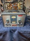
So going through my collection I actually found an RF generator! I just have no idea how it use it lol.

I’m 27 so all of this stuff is way before my time, I love learning though. I guess my first question will be, will this piece work and what kind of cable do I need for it?

Follow up questions will be what do the knobs do… RF ATTEN Coarse/Fine. MOD/AF. Etc

This is pretty exciting

Thank you so much!!!
 
That RF generator would be a good project. Unfortunately it won't work for a broadcast FM tuner. It only goes up to 30MHz. So it's good for ham HF radios but not what you need.
 
The A and C range here, I was under the impression that was FM and AM range. Is that not the case?

It’s all very confusing at the moment lol
 

Attachments

  • IMG_6543.jpeg
    IMG_6543.jpeg
    121.8 KB · Views: 6
on the bottom dial, kc stands for kilocycles which equals kilohertz in today speak. On the top dial, mc is megacycles. Same thing. Those are just frequencies. So the C range is good for AM broadcast receivers. It only goes up to 30 mc (MHz) though and you need 108MHz. Also, I don't see anything about FM on there so it probably does AM only. Besides all that, there's a good chance that generator needs some work if nobody's gone through it fairly recently.
 
on the bottom dial, kc stands for kilocycles which equals kilohertz in today speak. On the top dial, mc is megacycles. Same thing. Those are just frequencies. So the C range is good for AM broadcast receivers. It only goes up to 30 mc (MHz) though and you need 108MHz. Also, I don't see anything about FM on there so it probably does AM only. Besides all that, there's a good chance that generator needs some work if nobody's gone through it fairly recently.
I see now, Thank you so much!

i'll be on the lookout for another one.
 
This one below does everything you need except for stereo.
 
Back
Top Bottom