• The move to the new server is done. There are some software and database maintenance updates in process. This has us passing the hat around to help out. We appreciate any donations. Seriously, even a dollar helps. The payment page may be found here - https://www.audiokarma.org/support.html

Fisher KX-100 Blown Capacitor Help!

3105_ns

New Member
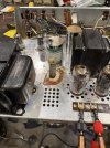
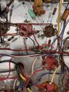
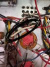
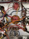
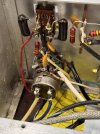
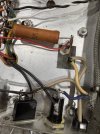
IMG_2293.jpegIMG_2296.jpegIMG_2292.jpegFirst time poster and I need help please. I aquifered a KX-100 a few months ago and have been reading the threads about restoration, re-capping, etc.

I have been cleaning it, accidentally flooded the volume pot, and took it apart, cleaned it, and covered the carbon with F100 and metal parts with D100.

One channel was not playing when I bought it, and after the volume pot restoration, I was still having problems.

I ordered new power caps from Hayseed Hamfest and was so excited last night when I turned it on and had full power to the left channel.

The right channel was still quiet, I tried to turn it all the way up and I would get some sound, and when I pushed in on the pot while changing the volume it would make more noise at the top. Exciting because it wasn’t a transformer and I might have made a mistake with the pot that I can fix again.

I also experimented with changing the position of the 7868 tubes to see if that was the channel issue, which is was not.

To the crux of the matter- I turned the amp on this morning to test again and to let it run longer. I went inside to help with lunch prep, came back out 15 minutes later and my beautiful new C1 cap had blown up. Power was still on, the fuse had not blown, and I can’t see anything underneath that was leaking and could have caused this.

What did I do wrong? Bad soldering, a snaller cap or something else blown that I couldn’t see?IMG_2289.jpegIMG_2294.jpeg
 
Register to hide this ad
For a new Capacitor to self-destruct like that it would have to have been installed backwards which based on the picture doesn't seem to be the case. If A/C was applied across it the likely result is the same, if SD1 or SD2 diodes were shorted it would cause problems but the amp would have hummed like mad if that was the case and in either case the fuse would have blown, Check to make sure the proper size fuse is installed, have a funny feeling the one installed is too high a value to protect against this type of destruction. Consider building a Bulb tester or obtaining a variac for initial testing.

Also some of the solder connections on the Hayseed caps look a bit suspect, confirm that they are making the proper connection.

Good luck!
 
Hi Ritchie- thanks. It is a 3.2 slo blo, and the amp’s power stayed on after it blew. I’ll check my solder connections as well.
 
On these Fisher units the consensus is that 3.2A is too large a fuse given the power rating of the amp. Been a while since I worked in one but I believe a 2.0 Amp fuse would be more reasonable in this particular amp. Also check/replace the SD1 and SD2 diodes as that is a prudent thing to do with these amps.
 
Backwards cap or shorted diodes would be my guess as well. Not too many things can make one blow up that bad and that quick. A shorted diode would make it hum pretty horrible though so I suspect you'd have known that.


I think the original fuse was as big as it was to deal with inrush, but I tend to agree that a lower amp slow-blow is a better fix. Especially if its got a thermistor in there, the inrush becomes much less of an issue.
 
KX-100 is an integrated amp. I use a 2A on my receivers(400's and 800-c's) which use 1/2 again more amperage. Also use a 2A on my X-101-B. I agree a 2A would be more in tune with what should be used on the KX-100. Especially with an inrush limiter being used. Use an inline or inductive ampmeter and see how much amperage it uses at cold startup (after you fix it). Then use the next highest fuse rating closest to your max amperage.
 
It certainly helps when you connect from a wire from R72 to the diode! ‍
 

Attachments

  • IMG_2534.jpeg
    IMG_2534.jpeg
    173.9 KB · Views: 8
Last edited:
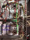
Also, I understand that that the 10 ohm resistor goes across 3 and 6, but I have been studying every photo in here and cannot see where the 100k from pin 1 for the grid screen ends at and where it is bussed. Would someone be able to attach a closer up photo of the buss and where the it is grounded? I am not going to do the ibam but am going to do the .068 and 230k adjustment. Thank you!
 

Attachments

  • IMG_2532.jpeg
    IMG_2532.jpeg
    201.7 KB · Views: 4
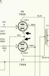
10 ohm DOES NOT go between 3 and 6. Cathode resistor comes off PIN 3 on ALL output tubes. Remove the lead and connect the resistor to PIN 3 on one side, and the lead on the other. Do this for each tube. DO NOT GROUND THEM. (see picture below. Only one channel for brevity).

NO Need to change output coupling cap value or grid return resistor VALUES. Cathode bias grid return resistor MAX VALUE on Tube data sheet is 1MEGOHM. The change is only relevant on Fixed bias (receivers) as that tube MAX VALUE is 300KΩ.

Use the 7868 screen resistor mod instructions at the bottom of this thread post https://audiokarma.org/forums/index...-parts-needed-for-fishers.327561/post-6480170 You can trace this lead back to the cap from the 1st output tube. Usually ORANGE in color. Open up the bundle as necessary.

11-16-2014Revised to show 7W resistor 1.2K to 1.5K depending on model unit. Tube pin 1 on 7591, Tube pin 8 on 7868.

On 7591's There is an improved setup. Thanks to Dave Gillespie for the improvement.

NOTE: This also works for Sansui 1000A with a slight modification (pairs are physically separated so screen lead is bifucated at the 1st pair closest to the main Power supply caps). Other than that it's identical. On the Sansui disregard the #4 instruction below as it doesn't have the 7W resistor.

7591 ONLY IMPROVED SETUP
1.) disconnect the old buss wire from the tubes. cut and remove the buss wire from between the output tubes.
2.) run a new wire of sufficient length to daisy chain the tube sockets at pin 1.
3.) install a 100ohm resistor to each tube socket from pin 1 to pin 4. Pin 1 is not used and is not connected internally.
4.) connect flying end of the 7W resistor to one of the center tubes. PIN 1. It must be before the 100ohm resistors.
5.) Connect the new buss wire to each tube's pin 1 in turn. Solder all connections.
Larry

7868 ONLY IMPROVED SETUP (Similar to 7591 except for Pin #)
normally.
1.) Same
2.) Change to Pin 8
3.) resistor to pin 8 to pin 1. Pin 8 is NOT used normally
4.) Connect the 7W resistor to one of the center tube pin 8.
5.) Same except for pin 8.

ScreenHunter 80.jpg
 
Hi Larry-

Your and Dave’s posts have been super instructive, thank you!
and I have read through all of the posts multiple times and have an understanding of the why, I want to make sure that I am doing it correctly.

I am staying with the 7868’s for now as I belong to a ham club and just had 500 tubes donated, with a lot of 7868’s in there

10 ohm replaces the jumpers from 1-7, not 3-6, sorry
100k is placed before pin 3 from R71? Or only on the jumpers between and then after pin 3 going to R70?

And if I do not do the bias board, should R69 stay at 3.3k .5w, and R70 stay at 6.8k .5w as indicated on the instructions or change?

I have a 1k8 10w on the way for R71
R72 should also be 10w but stay at 2.5k
 

Attachments

  • IMG_2536.jpeg
    IMG_2536.jpeg
    110.5 KB · Views: 1
I will post photos when completed. I read through your drawing as well and it makes sense until I look down at my unit and start to work.

Thank you again!
 
Schematics are drawn linearly, but units aren't. So you have to do a bit of thinking about what you're looking at compared to the schematic. In other words don't rush! The inclination to hurry thru it can/WILL result in mistakes and possibly injury to you and the unit. And that no-one wants.
 
Back
Top Bottom