• The move to the new server is done. There are some software and database maintenance updates in process. This has us passing the hat around to help out. We appreciate any donations. Seriously, even a dollar helps. The payment page may be found here - https://www.audiokarma.org/support.html

Fisher philharmonic p-22 restoration

Hello AK,

Back for my second tube restoration. The first restoration was a small stromberg carlson console which I converted into a standalone amp (asr-110) for my office at home and the cabinet into a console for my records and living room audio equipment. It puts out 3(?) watts of pure single ended tube goodness, I love it.

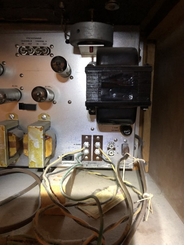
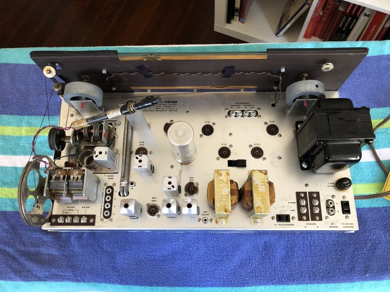
This is a fisher philharmonic p-22 that is really in great shape, the cabinet is beautiful, and the inside looks like it hasn't been touched. The construction is solid, and is honestly giving me alot of grief as I try and disassemble and remove the amplifier/radio. The chassis seems to be attached to the cabinet by 4 bolts around nails, and they are in a very tight space. I have a question that I am hoping someone in the community who has worked on fisher consoles could answer:

1. Any tips on disassembling the console and removing the amplifier?
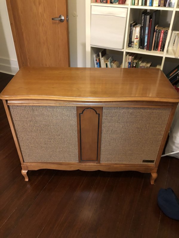

and the offending bolt/nail:
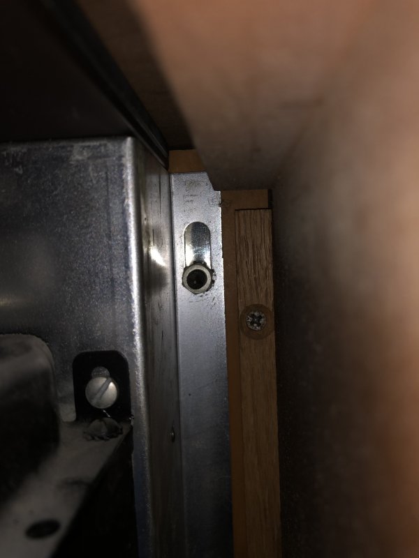
How do you get anything around that to unbolt it?

Thanks!
 
Register to hide this ad
Deep socket, extension. 3/8" drive will be too big, use a 1/4" drive set. Amp should rotate out from bottom toward the back.
 
$8 at home depot later, and success!


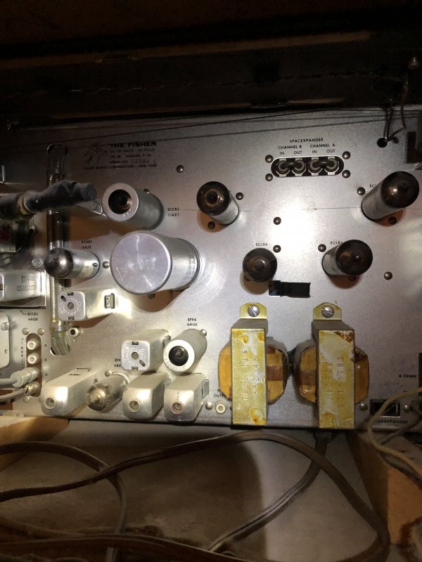
There are alot of ceramic capacitors, which I am assuming will be still within tolerance. Can I test capacitors in circuit, or do I need to desolder one lead first? I am planning on:

1. replacing ac cord with a three-prong
2. adding in-rush thermistor, I don't see one
3. replace can capacitor
4. replace electrolytic capacitors

There are some capacitors on the parts list I have labeled "molded". What are those? Do I replace them with film capacitors like orange drops?

Thanks!

Also, should I be replacing anything in the radio section? I have heard that can affect the tuning.
 
Molded caps are the black plastic ones. They have a high probability for seam cracking and leakage. Any film Cap of equivalent value and a higher voltage is fine.

Leave the cord as is. Grounding the chassis with a 3 prong cord can lead to ground hum. Better to put a polarized plug on it. Hot side to switch.
 
@larryderouin I had a question you might be able to answer. There are inputs to add the space expander into the signal path. I understand that to be a reverbation unit that Fisher used to sell. Is this essentially a pre-out? Could you use this to send a signal to another amp? Or to add an eq into the system?
 
Literally No, No, and No as it sits. It would probably take a lot of modifications that would need to be designed, tested and proven out. And the Philharmonic is a very basic unit. It wasn't designed for add on's except for one Phono, and a source on the Aux.
 
With a bit of effort those jacks could be re-purposed into that but it would probably need the buffer amp mod Dave developed for the bigger receivers.
 
Alright, well then I will leave it alone.

I am puzzled about one thing though. I thought this was the Fisher Philharmonic II (specifically the p-25X-P), which has the P-22 chassis, but when I got the schematic for it, it states the electrolytic is a 40-40-40-20. The cap on my unit is a Sprague TVL-4475 which is a 40-40-40-40. Would there be any reason why there would be different caps used? My guess is that this would not make much of a difference, but let me know if I am mistaken.
 
guess is either someone changed it in the past, or it was a running change during production. Probably not going to make any functional difference though.
 
Definately a replacement. FISHER never used Sprague Electrolytic Can caps to my knowledge. A 40-40-40-40 is a reasonable replacement tho. I would change it to be on the safe side. It probably dates from the 70's to the 80's and is way past it's expiration date. Cheap insurance. Either pick up a 40-40-40-40 450V @ AES or get a custom built to original spec by Hayseed Hamfest. Price is a wash btwn the two.

https://www.tubesandmore.com/products/capacitor-ce-mfg-450v-40404040-f-electrolytic $38.80ea
www.hayseedHamfest.com (Request a quote for the one using the spec from the manual) On the old cap, note the cutout shape next to the value/voltage/etc (top to bottom) and make sure you tell Tom or his son (who's running the Co now.)
 
Ok, thanks for the clarification gadget and larry!

I ordered the electrolytics and film capacitors from mouser, and I requested a quote from hamfest.
 
update: replaced all the electrolytics, can, paper, and wax capacitors. Built a dim-bulb tester and brought the radio back to life! It sounded awesome. I ordered some new dial lamps due to one being out, followed the advice of another fisher thread on AK pointing to an ebay seller.

I noticed that the dial glass is glued on to the chassis of the amp, but is also partially open in the top and bottom to allow for the am and fm dials. Do people remove the glass and clean it? Is there a general consensus on the best way to go about that?

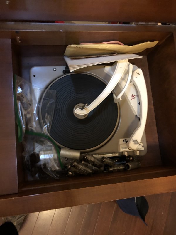
My next step is to replace the capacitors in the crossovers and then see how the old garrard turntable is doing. Then it should be good to go after some furniture polish. Not sure what I am going to do with it once its done, don't really have any place for it!

IMG_6628.jpg
 
if you remove it, be extremely careful. The letters are easy to remove. I have a damaged section of dial on a Sherwood from this.
 
if you remove it, be extremely careful. The letters are easy to remove. I have a damaged section of dial on a Sherwood from this.

Ok, I think I will just leave it alone for now. I really love restoring these old tube pieces. I was wondering, when you restore valve equipment, do you install an in-rush current limiter? I did that for my last amp, but forgot to order one this time. I am wondering if is necessary for a receiver in good working order.
 
I do. Fishers in particular have a power switch that is prone to failure so anything that will help it live longer is a good idea IMO.
 
The Dial is not glued in. 4 screws with tabs over the glass hold it down. There is a square rubber gasket running down the sides that after 55+years of heat and cool cycles, and other environmental factors has adhered to the glass and the metal back, An X-Acto knife with a #10 scalpel blade can be slipped between the glass and gasket to remove the glass.

Like gadget said, extreme care is needed to keep lettering intact.
 
Hello all,

quick question: I am installing a thermistor onto the hot ac line, but I just wanted to double check with people who I am sure have more experience reading diagrams than I do. I am including the relevant section to of the wiring diagram.
Screen Shot 2020-11-20 at 5.53.58 PM.png
Normally I assume the fuse and the switch will be wired in series in the hot AC line of the amp. This fisher seems to be different?? Am I correct in understanding the diagram to read as the hot ac line is "top" line coming from the ac plug? This would suggest I put the thermistor after the fuse and before it enters the transformer?

Thanks!
 
Back
Top Bottom