• The move to the new server is done. There are some software and database maintenance updates in process. This has us passing the hat around to help out. We appreciate any donations. Seriously, even a dollar helps. The payment page may be found here - https://www.audiokarma.org/support.html

Fisher RS-2010 Receiver Heat Sinks

Brivan

Well-Known Member
I purchased a Fisher RS-2010 receiver that was in protection mode and discovered D11, D13, D15, D17, Q13 & Q15 were all bad. Prior to that I had removed the left channel STK-0080II since it showed 49 volts on the audio output. Also prior to my discovery of the bad diodes and transistors, I replaced both STK-0080II modules with genuine Sanyo modules, only to discover the receiver was still in protection mode with 49 volts on the audio output of the left channel STK module. At this point, I discovered the bad diodes and transistors. I will have replacements tomorrow and am hoping the STK left channel STK module survived. No smoke or funny popping noises when I last powered it up. I also had audio coming from the original STK modules when probed with an audio tracer, so I'm hoping the problem was strictly with the bad diodes and transistors (bu I somehow doubt it).

I used Quicksilver heat sink compound on my two replacement STKs since they make direct contact with the heat sink. When I pulled the amp board and STKs away after finding out I had other bad components on the amp board, I noticed the heat sink compound pattern behind the left channel STK wasn't making good contact with it. And I put a fair amount of torque on the mounting screws (keeping in mind I was tightening down on plastic).

From the common failures these modules seem to exhibit from overheating when installed in a Fisher RS-2010, I thought maybe the heat sinks were warping and decided to mill down the contact area where the STK meets the heat sink. It came out pretty good, I think.
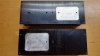
Fisher RS-2010 Receiver Milled Heatsinks.jpg

The milled surface is not smooth like the original was, but it's even. My theory is that, with both the rear surface of the STK and the heat sink being smooth, the heat sink compound would compress into a thin layer at best, not allowing much for metal-to-metal contact between the module and the heat sink. With the rougher milled surface, the heat sink compound will be pushed into the "pits" and the STK and heat sink will make direct contact on the "lands". Just a theory - we'll see how it goes.
 
Register to hide this ad
May I ask where you found those?

Nice work on the heat sinks!

Thanks,

chazix
They were an Ebay purchase. I assume they're Sanyo originals - they have numbers stamped on the backside of the heat sink. Thanks - hopefully that modification to the heat sink will help. If not, it looks like the heat sinks can be swapped between left and right sides, which will allow me to use the factory heat sink surface again, if needed.
 
I got the bad diodes and transistors replaced, then reinstalled the amp board and STK modules. Getting about +175mV on the output of one module and -175mV on the output of the other, which seems a little high, but I definitely eliminated the 49v from the left module output. Still no relay click. Hmm. I measured about 19.5vdc across the relay coil - should be enough to pull it in, but who knows? 22v on one side of the coil to ground and 3.8v on the other side to ground - looks about right, according to the schematic. I wrestled the cover off the relay to see if it was bound up and check the internal coil wires. When I powered the receiver back up, the relay happily clicked in. Huh. Guess it was gummy. Sprayed the contacts with DeOxit and worked them back and forth and put the cover back on. Receiver sounds good (except for dirty pots).

I got to looking at the STK modules and it didn't look like the right-channel module was sitting flush against the heat sink. Closer observation revealed that the amp board was sitting up against the heat sink and may be preventing the modules from being seated properly in their now-deeper milled cavity (about .004"). I pulled both heat sinks and saw that wasn't really the problem, but heat sink compound was still only making contact on about half the surface on both modules - mostly in the middle on the outsides. Heavy sigh. I decided to scrap the milled cavity idea, swapped left and right heat sinks, and used a fresh place to mount the STKs (nice that the heat sinks are left-right swappable). One more application of compound, reassembly, pots cleaned, tuner aligned and we're good to go.

As stated, I have +175mA on one channel and -175mA on the other with volume all the way down (no load). The manual makes no reference to what this measurement should be, so I'm hoping it's about right. If anyone knows, would you mind cluing me in? Also, the AM reception is nothing to write home about, although the FM reception is decent. I don't know if that's typical of these receivers or not, since this is my first one. And, finally, I replaced all the old incandescent lamps (including function indicators) with LEDs. The function indicators were a little challenging - there's 14 or so altogether and it's hard to steer clear of wires when soldering. Glad it's done, though - looks nice!
 
I am finishing my RS-2010... I decided to treat the unit to RCS16 design STK-0080 replacement.

My STK experience pushed me to a better solution. Impressed to say the least.

My blown pack took out six components and the relay.

Remember your thermal paste is electrically conductive... not that it matters for your plastic STK pack (JFYI).

http://audiokarma.org/forums/index.php?threads/project-fisher-rs-2010.855391/

On your speaker terminals you want DC close to zero. Less than 30mV is a good goal.
 
I am finishing my RS-2010... I decided to treat the unit to RCS16 design STK-0080 replacement.

My STK experience pushed me to a better solution. Impressed to say the least.

My blown pack took out six components and the relay.

Remember your thermal paste is electrically conductive... not that it matters for your plastic STK pack (JFYI).

http://audiokarma.org/forums/index.php?threads/project-fisher-rs-2010.855391/

On your speaker terminals you want DC close to zero. Less than 30mV is a good goal.
Thanks for the info! I did some reading on RCS16's design. I'd like to try it on another receiver - I was getting my feet wet on this one. I kinda figured 175mV was too high. I'll recheck and see what I can figure out from there. I love the FM tuner on this receiver - very "live"-sounding! I decided to go with the QuickSilver once I saw that there was no electrical isolation between the backside of the STK module and the heat sink.
 
I am finishing my RS-2010... I decided to treat the unit to RCS16 design STK-0080 replacement.

My STK experience pushed me to a better solution. Impressed to say the least.

My blown pack took out six components and the relay.

Remember your thermal paste is electrically conductive... not that it matters for your plastic STK pack (JFYI).

http://audiokarma.org/forums/index.php?threads/project-fisher-rs-2010.855391/

On your speaker terminals you want DC close to zero. Less than 30mV is a good goal.
I'm back at the RS-2010 after a brief hiatus. Is the Ovdc at the speaker output terminals at all adjustable (by replacing possible bad components) or is it determined solely by the STK-0080? Any insight you could give would be appreciated. Thanks!
 
Ki
No. Their is no offset or bias adjustment.

Upgrade the caps... change the STKs.
Kinda what I thought. Bad thing is that I just replaced both STKs with new replacements from an Ebay seller with good ratings. Both STKs were stamped on the backside, like the OEMs reportedly are. Cap-replacement-wise, I would assume you're referring to the amp board (primarily), then power supply board, etc, as needed? Thanks, again for your help!
 
Maintaining zero DC at the amplifier outputs is not the job of the power packs - if things are more or less working, DC offset is determined by the amplifier input stages.
 
Are both your originals STKs dead?
The left STK was thought to be impaired because of the rail voltage present on the output. Funny thing was, when I used a signal tracer on the STKs, both sides were producing audio, but I assumed the left-side STK was bad because of the high output voltage. When I replaced both STKs, I still had rail voltage on the left side and discovered several other components that were bad on the left side (which were all replaced based on replacement info obtained here on AK). Once those components were replaced, the protection relay engaged and I still had around 175mV present at 0 volume on both sides. Audio sounded fine, but I was left wondering if my original STKs were okay. Also, the original STKs were mismatched, with the left-hand one not having any stamping on the backside (but an additional number in the upper right-hand corner of the front side) and the right-hand one having an assumed OEM stamp on the back. I have since tossed the original LH module, but kept the original RH module.
 
Maintaining zero DC at the amplifier outputs is not the job of the power packs - if things are more or less working, DC offset is determined by the amplifier input stages.
Good to know - I would assume this is likely referring to the components on the amp board?
 
Good to know - I would assume this is likely referring to the components on the amp board?

(Sheepishly,having not actually looked at a schematic for this particular model 'til now...) Yes, primarily the differential amplifiers, paired transistors Q005/Q007 and Q006/Q008.

Hmm, I see they call for 83mV to be expected at the base of Q007 - that strongly implies that a similar voltage is also expected at the output of the amplifier. That is, a DC offset in the neighborhood of 80mV would be normal. Odd.

Or am I even looking at the correct schematic? On the one I'm looking at (sourced from elektrotanya, but apparently ripped off from hifiengine), the power packs do not appear to be equivalent to STK0080IIs. Mine shows them as being STK0105s, and shows them as being a two-stage emitter follower configuration. The STK0080II, a three-stage follower, would probably function, but it's not a substitution I would make lightly.

Obviously I'm confused, so you might have to take my input with a grain of salt.
 
Yeah. Q5-6-7-8 are the input differential pairs (2sa1016) IIRC. If they are mismatched due to heat, wear, etc., the offset is increased. I'd also replace Q17-18-19-20 (2sc2362 complimentary to 2sa1016)with matched replacements (matched to Q5-6-7-8). replace with KSA1015 and KSC1845. The KSA1015 is heavier duty than the ksa992, but not as low noise.

Chazix. IIRC the RS-2010 apparently came from the factory with either the 0080 or the 0105 chips in them. I've seen both in the 2010, with no change in circuitry.
 
Yeah. Q5-6-7-8 are the input differential pairs (2sa1016) IIRC. If they are mismatched due to heat, wear, etc., the offset is increased. I'd also replace Q17-18-19-20 (2sc2362 complimentary to 2sa1016)with matched replacements (matched to Q5-6-7-8). replace with KSA1015 and KSC1845. The KSA1015 is heavier duty than the ksa992, but not as low noise.

Chazix. IIRC the RS-2010 apparently came from the factory with either the 0080 or the 0105 chips in them. I've seen both in the 2010, with no change in circuitry.

Thanks for the good information, Larry. I've been looking into why my particular RS-2010 was equipped with STK-0080II modules, rather than STK-0080. It was obvious that at least one of them had been replaced prior to me buying the receiver, but now I'm wondering if the "II" modules should be in there at all. From the discussions I've read on AK, I've seen no references to an RS-2010 having the "II" modules. From the clip of the data sheet below, they are different and, strangely, it looks like there's nothing more than a couple of external capacitors connected to the "II" module. Can you shed some light on this?

Capture.JPG
 
Last edited:
Yeah. Q5-6-7-8 are the input differential pairs (2sa1016) IIRC. If they are mismatched due to heat, wear, etc., the offset is increased. I'd also replace Q17-18-19-20 (2sc2362 complimentary to 2sa1016)with matched replacements (matched to Q5-6-7-8). replace with KSA1015 and KSC1845. The KSA1015 is heavier duty than the ksa992, but not as low noise.

Chazix. IIRC the RS-2010 apparently came from the factory with either the 0080 or the 0105 chips in them. I've seen both in the 2010, with no change in circuitry.
Okay, I first replaced the STK-0080II modules with STK-0080 modules. Photo below. I measured around 23mV on the output of the right channel (much better!) and around 145mV on the output of the left channel - still too high. Next, I replaced Q5, Q6, Q7, Q8, Q17, Q18, Q19 & Q20 with the replacement transistors as noted in your post - nice that the pin arrangement is the same as on the originals. I still have about 23mV on the right channel and about 34mV on the left channel. The left channel is probably within acceptable limits, but I wish it was a little lower.
Fisher RS-2010 Receiver New STK-0080 Modules.jpg
 
Usually as long as the offset is <50mV, you're good. 50mV is generally accepted as the upper limit for a very good offset. Having said that, obviously the lower the better. But as it's not an adjustable setting for STK's that may as good as it gets.
 
Usually as long as the offset is <50mV, you're good. 50mV is generally accepted as the upper limit for a very good offset. Having said that, obviously the lower the better. But as it's not an adjustable setting for STK's that may as good as it gets.
Okay. I'd decided that what I had was good enough. After running it for awhile, the left channel settled into about 28mV, with the right channel still being at around 24mV. Good enough for me.

BTW I did clip off the tailings of the module leads after I took that pic - probably wouldn't have mattered considering the height of the amp board standoffs, but they kind of creeped me out like that.

Also, I'm glad I had to separate the STK modules from the heat sinks - it gave me the opportunity to see where the heat sink compound didn't make contact between the sink and the modules. I applied a little extra in those areas before remounting everything.

I think those STKs sound just fine. I have an integrated Zenith receiver (same kind I had back in high school) that contains a dual-channel single module - I've always liked the sound of it.
 
But as it's not an adjustable setting for STK's that may as good as it gets.

We're talking about Darlington "power pack" STKs, right? There's no reason that an amp that uses them for the output stage couldn't have an offset adjustment. It just doesn't happen to be adjustable in the Fisher, so your suggestion of looking at the input stage transistors in hopes of getting more favorable matching was pretty much the only way to go. (And it worked pretty well - time for the victory dance, I'd say!)

Now, output stage bias (aka idle current aka quiescent current), on the other hand - that is what's non-adjustable with any Darlington power pack that I know of.

As an example, several of Yamaha's CR-x40 series use STK-like parts (Yamaha-labeled Sanyo encapsulated modules) for input and output stages. They do have adjustable offset, but not bias.

Cheers,

chazix

(Edited after realizing it was also larryderoin who suggested the input transistors.)
 
Last edited:
Back
Top Bottom