Dave,
Thanks for the explanation. It helps a bit but I'm apparently a little dense.
First:
OK-So these components were all replaced during the rebuild with matched 5% mil spec Allen Bradley carbon comps and a tested high temp 96p series vit q capacitor. What threw me off was that when I used the Fisher method, there was no difference in what I measured at the speaker terminals regardless of where the ACB control was set, either full CCW or full CW. Perhaps my meter was not sensitive enough for the test as described. (Aw ****, I just realized I may have left the meter set to read DC which would explain my results taken at the OPT secondary's. I'm leaving this in the post for the benefit of others who may make the same mistake).
Looking at the schematic it seemed like a logical place to focus my attention might be to have the plates of each section of the AF/PI 12au7 tube provide equal voltage to the output stage top and bottom. At least the position of the ACB control was affecting the measurements taken at these two points. I suppose this approach naively assumes that everything after the AF/PI stage must function dynamically balanced and why using a distortion analyzer keeps popping up in articles I read about ideally setting the ACB properly. Since I did actually match and replace each of the resistors and caps to the output stage, perhaps balancing the 12au7 plate voltages at least provided me with a good starting point, the final adjustment remains to be seen when I use an AC meter at the output this time around. (What a dumb ass I am that it took me two days to realize).
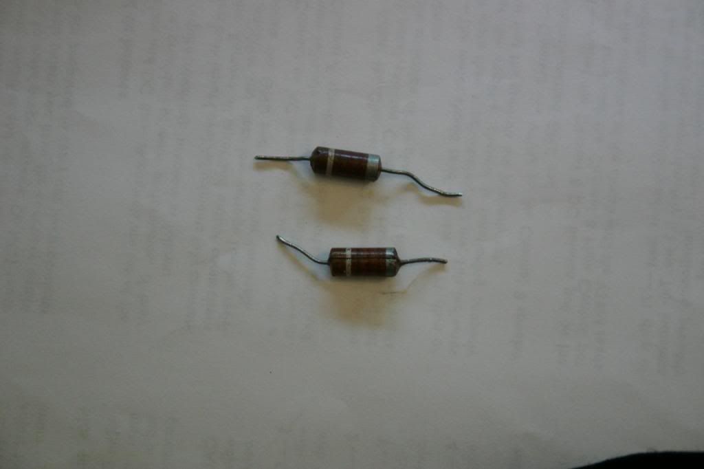
The other issue-the 220pf capacitor coupling the 410v supply directly to the plate of the ECC82 AF amp stage (and not directly to the plate of the complementary PI). If I understand you correctly, this is a local feedback for the output stage rather than global feedback for the channel. How would value drift affect the amp? It's impossible to source a 220pf bumblebee or paper cap, all that's available is either silver mica or ceramic. Every other pf range capacitor in the amp is ceramic, were the bumblebee's more stable than ceramic and should I replace the bumblebees with silver micas if I suspect the bumblebees have become damaged or otherwise out of tolerance?
More succinctly, why do you thing Fisher put a bumblebee cap right there and only there? And if damaged or suspected damaged, WWDD? Do you think a silver mica would add clarity to the sound compared to a bumblebee?
Lastly, about the observations made regarding the orientation of the mains transformer on the X-1000. I thought the optimal orientation for any mains transformer was to place it so the strongest magnetic lines of force emitted were aimed 90 degrees away from the OPTs to minimize flux interference. The placement of the mains transformer on the SA300 puts the lamination plates at 90 degrees to their respective OPTs in the same vertical plane directing the lines of force in different directions whereas placing a mains transformer on it's side still allows the lines of force to cut across the lines of force of the OPTs, albeit in another plane. Wouldn't the orientation used on the SA300 be the most ideal?
Your thoughts?
Rich
Thanks for the explanation. It helps a bit but I'm apparently a little dense.
First:
There is very little that can go wrong with the AC balance function. Check that the 30 vac is being applied to the wipers of the AC Bal controls via the coupling cap, the value of the 3300 ohm resistors supplying the B+ to the wipers, and that the switch, and coupling cap are all operational. There's really little that can go wrong with the circuit.
OK-So these components were all replaced during the rebuild with matched 5% mil spec Allen Bradley carbon comps and a tested high temp 96p series vit q capacitor. What threw me off was that when I used the Fisher method, there was no difference in what I measured at the speaker terminals regardless of where the ACB control was set, either full CCW or full CW. Perhaps my meter was not sensitive enough for the test as described. (Aw ****, I just realized I may have left the meter set to read DC which would explain my results taken at the OPT secondary's. I'm leaving this in the post for the benefit of others who may make the same mistake).
Looking at the schematic it seemed like a logical place to focus my attention might be to have the plates of each section of the AF/PI 12au7 tube provide equal voltage to the output stage top and bottom. At least the position of the ACB control was affecting the measurements taken at these two points. I suppose this approach naively assumes that everything after the AF/PI stage must function dynamically balanced and why using a distortion analyzer keeps popping up in articles I read about ideally setting the ACB properly. Since I did actually match and replace each of the resistors and caps to the output stage, perhaps balancing the 12au7 plate voltages at least provided me with a good starting point, the final adjustment remains to be seen when I use an AC meter at the output this time around. (What a dumb ass I am that it took me two days to realize).
The other issue-the 220pf capacitor coupling the 410v supply directly to the plate of the ECC82 AF amp stage (and not directly to the plate of the complementary PI). If I understand you correctly, this is a local feedback for the output stage rather than global feedback for the channel. How would value drift affect the amp? It's impossible to source a 220pf bumblebee or paper cap, all that's available is either silver mica or ceramic. Every other pf range capacitor in the amp is ceramic, were the bumblebee's more stable than ceramic and should I replace the bumblebees with silver micas if I suspect the bumblebees have become damaged or otherwise out of tolerance?
More succinctly, why do you thing Fisher put a bumblebee cap right there and only there? And if damaged or suspected damaged, WWDD? Do you think a silver mica would add clarity to the sound compared to a bumblebee?
Lastly, about the observations made regarding the orientation of the mains transformer on the X-1000. I thought the optimal orientation for any mains transformer was to place it so the strongest magnetic lines of force emitted were aimed 90 degrees away from the OPTs to minimize flux interference. The placement of the mains transformer on the SA300 puts the lamination plates at 90 degrees to their respective OPTs in the same vertical plane directing the lines of force in different directions whereas placing a mains transformer on it's side still allows the lines of force to cut across the lines of force of the OPTs, albeit in another plane. Wouldn't the orientation used on the SA300 be the most ideal?
Your thoughts?
Rich