• The move to the new server is done. There are some software and database maintenance updates in process. This has us passing the hat around to help out. We appreciate any donations. Seriously, even a dollar helps. The payment page may be found here - https://www.audiokarma.org/support.html

Fisher TA-600 Restoration

mrphilco

Well-Known Member
After procrastinating for two (or has it been three?) years...I decided that it is time to do something with my prized 1959 The Fisher TA-600 stereo receiver.

ta600_001.jpg


Disassembly

The receiver is held inside its metal cabinet by the four screws which go through each of its four rubber feet. There are also four small wood screws underneath; don't bother removing these as they only hold two wood strips which help to hold the TA-600 in place inside the cabinet. It is the four long machine screws which pass through each of the four rubber feet which need to be removed in order to remove the receiver from the cabinet.

Once this is done, the receiver may be pushed/pulled from the cabinet.

ta600_002.jpg


Here is how it looks outside the cabinet.

ta600_003.jpg
 
Register to hide this ad
The front panel is made of brass. The panel on my set is in excellent shape with only a few minor scratches.

I want to keep it that way, so I pulled the knobs...

ta600_004.jpg


...then removed four nuts on the FM tuning, AM tuning, bass and volume shafts. Once the four nuts were removed, the front panel pulled right off and was put away for safe keeping.

I wanted to remove the dial glass also, but the brackets holding the dial glass do not appear to be easily removable - each bracket is held in place by tabs which are folded over in back of the face plate.

So...I will just have to be extra careful.
 
Last edited:
A look at the top of the chassis:

ta600_005.jpg


The bracket which holds the AM ferrite rod antenna is made of plastic, and was broken in shipment to me. :cry: I will glue it back together with epoxy, and I will put a piece of plastic across the back of the broken area to give the bracket extra strength. I will probably do that when I am close to being finished with this unit.

A look underneath.

ta600_006.jpg


Question:

Would you recommend replacing the brown molded Mylar caps, or leaving them alone? (They look like Orange Drops, only brown.)

All of the electrolytics will be replaced.

I will also replace the line-to-ground "Black Beauty" death cap.

I did not intend to bother the ceramic caps.
 
I spent some quality time with this receiver next to my Heathkit TT-1 mutual conductance tube tester.

Unfortunately...nine of its 22 tubes test bad (extremely, extremely weak). A real shame, because until this afternoon it still had all 22 of its original Fisher branded tubes.

One of the nine is the 5AR4/GZ34 rectifier.

One 6AU6, two 6AQ8/ECC85, one 6AJ8/ECH81.

And...naturally...all four 7189 output tubes. $$$

:(

An observation: My TA-600 is serial number 459xx, so it may have been built in 1960? I have read that some TA-600 face plates have a date stamped on the back of the face plate. Mine doesn't.

I have the proper original Fisher service manual for serial numbers 40001 - 49999. It came with the receiver.
 
The replacement tubes are slowly rolling in...

ta600_007.jpg


Two Raytheon 6AQ8/ECC85 (made in Japan), one Siemens ECH81/6AJ8 (Germany - not pictured), one Sovtek 5AR4/GZ34 (Russia) and four 6П14П (Soviet Union). Still waiting for a 6AU6 from California.

Unfortunately, one of the 6П14П tubes did not survive shipment - it isn't broken, but the filament is intermittent. When I put it on my tube tester's Line Test, I can watch the needle go back and forth as the filament goes on and off. I've contacted the seller and hope to receive a replacement.

In the meantime...I also purchased four 6П14П-EB tubes from a seller in Ukraine. I did so in case the 6П14П tubes I now have do not work out for some reason, although three of the four tested quite strong and I think the seller will probably give me another with no hassles.

Now...I have to get my electrolytic info together and contact Hayseed Hamfest for a quote on three twist-lock electrolytic cans.
 
Another tube arrived today, a 6AU6WC military Sylvania.

So I then decided to try an experiment.

I reinstalled the original very weak 7189 Fisher tubes, hooked up a pair of speakers, and put the TA-600 on the Variac.

By 90 volts I could see the FM tuning eye (I had it set to FM), and I was obviously tuning in stations as the eye was opening and closing as I tuned across the FM band. So by visual indication, the tuner appears to be OK. I did switch it to AM and also saw the AM tuning eye opening and closing as I tuned across the AM band, though not as much as on FM.

One problem though.

No music...no talking...no noise...nothing.

Silent Night.

Or, if you prefer, The Sounds of Silence.

???

I turned the Variac off and unplugged everything. The 5AR4/GZ34 was barely lukewarm, and the 7189s were cold.

Hmmm...sounded like no B+ to the output tubes to me.

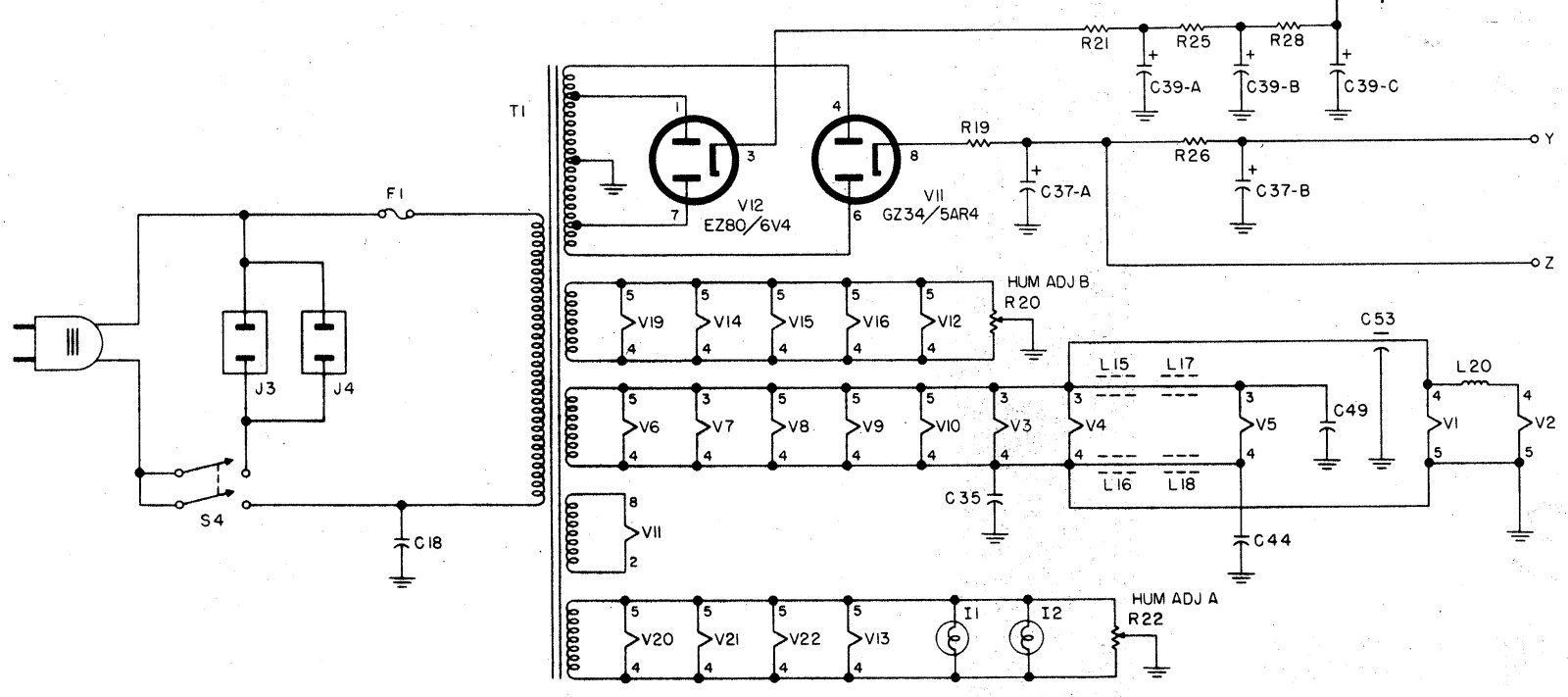
Consulting the schematic, I noticed that there is a 160 ohm, 10 watt resistor between the 5AR4/GZ34 cathode and the input electrolytic capacitor section.

You guessed it...that resistor is open.

I won't be doing any more Variac tests until after I replace the electrolytics and, of course, that burned out resistor. I'll also check the other power resistors to see if any others are open.

Back to the 6П14П...the seller readily agreed to send me a replacement.

I have my price quote from Hayseed Hamfest also, and the cost will be about what I expected it to be.

Yes, I could cut open the original cans and restuff them, but this is a special unit and I think it deserves the special treatment of new twist-lock electrolytics.
 
Schematics:

Tuner and power supply - Click Here

Stereo amplifier - Click Here

Here's the power supply - click to enlarge.


As you can see, with R19 open as it is, no B+ is going to get to the stereo amplifier. Point Z goes to the center taps of the audio output transformer primaries (and from there to each of the 7189 plates); point Y goes to the 7189 screen grids. Point Y also serves as the B+ source for the rest of the amplifier section.

While searching for more information about the TA-600, I found this thread:

http://www.audiokarma.org/forums/index.php?threads/ta-600-service-bulletin-early-version.676168/

I intend to perform the mods called for in the first post of that thread save for the part about 7199 drivers. I'm already using 7199s and had no intention of using adapters for alternate tubes, so point 3 in Dave Gillespie's post will not apply in my case.

I now understand why R19 is open in my TA-600 - the resistor was under-rated to begin with, and late production models switched to two 280 ohm 7W resistors in parallel to equal 140 ohms, 14W. I'm replacing mine with a 150 ohm, 20 watt resistor.
 
So the real work began:

ta600_008.jpg


I have replaced three electrolytics and some resistors, most notably R19 and R26.

ta600_009.jpg


Following the recommendations by Dave Gillespie in this thread, I changed R19 to a 150 ohm, 20 watt resistor. I added new terminal strips to hold R19 and R26, and to get their ends away from audio section wiring as Mr. Gillespie suggested.

ta600_010.jpg


A closer look at a couple of the 25 uF electrolytics I replaced, along with the resistors that also connected in the same areas:

ta600_011.jpg
 
Last edited:
A nice CARE package arrived in yesterday's mail from Iowa.

ta600_012.jpg


ta600_013.jpg


Three new Hayseed Hamfest twist-lock electroytics, custom made for the Fisher TA-600. This was my first order from Hayseed, and I must say these caps look great.

Installing the first one was easy:

ta600_014.jpg


The second can, C39, wasn't too difficult:

ta600_015.jpg


ta600_016.jpg


Next, I took a photo of C37 - just in case I forgot what went where, since so many wires and resistors connect to it:

ta600_017.jpg
 
Five hours later (you read that right)...

ta600_018.jpg


C37 is in place. All of the resistors that were connected to C37 were replaced with new ones. The 4.7K and 33K resistors look smaller than the originals but are actually 2W units (the originals were 1W).

In case you noticed - Yes, the white and yellow wires are now reversed in comparison to how they were wired previously. This is correct per Dave Gillespie (see this thread).

That was a lot of work! Time to relax. I have five more individual electrolytics and the death cap remaining to be replaced.
 
Good news...

So I set out today to replace the remaining individual electrolytics and the death cap.

I also used DeoxIT on all controls and switches, followed by FaderLube on all controls.

The death cap was easy. I replaced the original .01 uF "Black Beauty" line to ground cap with a modern safety cap.

Four small electrolytics...not so easy.

ta600_019.jpg


ta600_020.jpg


Hint: The new electrolytics are silver, made by Vishay-Sprague.

There is still one more to do. And it is going to be fun. NOT.

I turned the receiver over, connected two speakers, plugged it in through my Variac, and slowly brought it up to 115 volts.

It's Alive!

ta600_021.jpg


Those new Hayseed Hamfest caps certainly look good on top of the chassis.

ta600_022.jpg
 
...bad news

I let it play for several minutes, tuning across AM and FM bands, and it was sounding great.

All of a sudden, I started noticing a pronounced distortion in the sound!

I looked at the 6П14П tubes, and one of the poor little Soviet tubes had a glowing red plate.

I immediately turned the thing off.

:(

The distortion could be the result of audio coupling caps dying (I did not replace any of the brown caps that look like brown Orange Drops), but the glowing red 6П14П concerns me. It looks like I will be forced to install the Dave Gillespie IBAM mod in this receiver if I ever want to use it for any length of time.

It's probably a good thing I have another set of NOS-NIB 6П14П-EB tubes on their way here from Ukraine. (Maybe I should have bought two sets?)

Well, at least I made my goal of hearing this receiver play in time for my birthday (I actually beat that goal, having heard it for the first time last night). But this unit will require more work.

I need to order some CL-80 inrush current limiters for this receiver as well as my Fisher 400 and 500-B. I shall also order the necessary parts to build an IBAM board for this receiver.
 
Last edited:
I have a number of those brown shiny caps in Sherwood gear, and all of them have tested fine. Mine are ElMenco I believe, but I've also had good luck with Cornell-Dublier "brown drops". As with all things, your mileage may vary. I tested mine with an ancient Solar cap tester that would check them for leakage at rated voltage.

Did you install the cathode current monitoring resistors? I've had fairly bad luck with the Soviet tubes in terms of matching when just buying them direct from Europe. This one really sort of wants the tubes decently matched. Failing that, adding the bias adjustment board to dial them in closer should help somewhat.
 
Hi Gadget73,

Thanks. I was also advised by someone else on another forum to leave the brown caps alone.

I have the 10 ohm cathode resistors on hand, but have not yet installed them.

The set of 6П14П tubes currently in the set are used, tested and (supposedly) matched, from a USA seller. Hoo boy...It does look like I need to add the IBAM mod, doesn't it?

...I could also pull out the $$ and get the matched EL84Ms from Jim McShane...I've never bought anything from him but from what I have read, his reputation is excellent...
 
Last edited:
Ron. Swap the Redplating tube with it's mate. If the redplating follows the tube, the tube is at fault, if not then the coupling caps are at fault. These things run very hot when running stock, almost like a Sansui 1000A, and it's possible that the heat affected the coupling caps. Unfortunately mine is a 599xx series with 4 not 6 of the caps. I replaced them with Yellow Illinois caps. No problems with them or the Russian tubes. Got some Aluminium HVAC tape? If so overlay the side of the transformers that face the output and rectumfrier tubes. It will reflect some of the radiant heat from the tubes away from the transformers.
 
Thanks, Larry. I'll try that tomorrow evening.

I had some aluminum HVAC tape around here somewhere. I'll see if I can find it, else I'll get another roll. Good idea.

Regarding the yellow Illinois caps - did you use polyester, or polypropylene? Mouser doesn't stock the Illinois caps but Digi-Key does.
 
That's a really super job you're doing! No doubt you'll have it going in no time.

I do highly recommend that you install the IBBA modification. The output stage passes a significant amount of current, as in normal Fisher fashion, they use that current to light the heaters of the phono preamp tubes. If the current flow between the four output tubes has much imbalance to it at all, whatever tube is the current hog will have its plate show color in dim room light. The match between the four tubes either needs to be very tight, or you need the IBBA modification to equalize the current between the tubes to accomplish what the match will not.

Good luck with it!

Dave
 
Ron; I used polyester. I got them from AES at the time. I can't hear the difference between the polyester and polypropylene.
 
The brown drops are mylar I believe. I believe polyester would be the equivalent. Or just use actual orange drops. I also can't tell the difference honestly, but sometimes orange drops are harder to fit places because of the radial leads vs axial leads.
 
When I did mine, I tried O.D.'s at the time on the coupling caps for the output's. the .047uf 630v were too big to fit in without getting scrunched between the chassis and the bottom plate. Main reason I went with Illinois caps.
 
Back
Top Bottom