• The move to the new server is done. There are some software and database maintenance updates in process. This has us passing the hat around to help out. We appreciate any donations. Seriously, even a dollar helps. The payment page may be found here - https://www.audiokarma.org/support.html

Fisher X-100-2 safety mods and maybe more???

sbcrockett

AK Subscriber
Subscriber
Hello friends,

I thought it was time to start the upgrades on my Fisher X-100-2 and want to document the information and photos. I know there have been many such threads covering what I'm planning on doing but I'm not quite expert enough to translate the information in those other threads and apply them to this particular amp.

To start off, I will say that this Fisher was pulled from daily use and was sounding so great. It was a difficult decision to ignore the procrastinator voice in my head that said, if it ain't broke...but I felt that performing at least the safety mods to the unit now would extend the usable life and enjoyment of it. This seemed like a no brainer and maybe, just maybe, in the process, I might build up my nerve to go full on modder and install an adjustable bias circuit and...gulp...possibly EFB(tm) ala Mr. Gillespie.

I've got some questions now and will likely have many more down the road, so let me just recognize the fine people who have given me so much help up to this point. While I've learned a lot in the last year, I would be spinning my wheels much of the time if it weren't for all you guys and your expertise. Thank you so much for all the help I received last year during my Scott LK-72 restoration and in other threads along the way.

My plans:

1) Triac mod to prolong the life of the power switch. Please weigh in if you disagree but I believe this mod is pretty universally accepted as beneficial.

2) Screen stability grid resistors (with questions below)

3) Cathode resistor mod (also questions below). Even though I will only be able to measure each tube current at this point, I feel it would be beneficial to at least know if the output tubes are closely matched.

4) Hayseed Hamfest can caps are ordered and should show up soon. Someone in the past had wired in a replacement C1 without actually removing that electrolytic cap. From a thread earlier this year, larryderouin helped me figure out what was going on with that part and made a few other suggestions for component replacement and upgrades here:

https://audiokarma.org/forums/index.php?threads/any-fisher-expert-techs-in-the-pnw.890664/

5) Not sure if I need to change out the control grid resistors but they are 330K in this amp and I've read that others have changed them to 200K in other designs but I don't understand why.

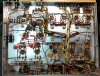
This amp has seen some work before I found it, mostly coupling cap replacement and the power supply cap mentioned above. I also installed a CL-80 to help with the inrush current last year. Along the way I'll also rework ugly solder, clean up flux and tidy things up but, for the most part, this is a pretty clean example:
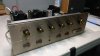
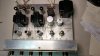
X-100-2_front.jpg X-100-2_top.jpg X-100-2_serial.jpg
IMG_20191108_054958425_HDR.jpg

Again, during these updates I'll be continuing to read up on Dave Gillespie's EFB(tm) mod or at a minimum IBAM. I just see the absolute value in getting an adjustable bias capability in this amp to extend tube life and improve performance. I hope keeping track of my progress will be helpful to others. I know it will certainly be a help to me just having a reference in one place.

First questions are about the cathode and screen resistors. I believe I will be removing all the jumper wires connecting pin 3 (cathode) and pin 9 (screen) on all four output tubes which are 6P14P-EB's at the moment? I've sketched up a drawing showing what I believe to be the intention:

fisher_x_100_2_resistors.jpg

Does this rough diagram look correct? Follow up questions are about the resistors themselves, mainly, 1/4 or 1/2 watt? Metal film or carbon comp? And, lastly, I understand one end of the buss bar will go back to the voltage connections but what about the other end? By the way, as the amp sits now, I went through and measured voltages around the power supply and the output tubes and everything is inline with the schematic so, the dream would be to install these mods and keep everything working well just like it is now.

I'm not exactly sure how to wire up the triac or where to install it. The underside of this chassis is pretty shallow and if I want to mount it near the power cord it'll be a tight fit. Photos and questions on that issue coming soon.

Thanks for reading!

-Steve
 
Last edited:
Register to hide this ad
Leave the grid control resistors be (unless broke or out of spec). The "replace the 330KΩ with 200KΩ" with the attendant coupling cap value change to .068uf is for FIXED BIAS UNITS ONLY using 7591 or 7868 tubes. As this is a 6bq5/7189 amp, it's not relevant.

Screen and cathode resistors.
1.) Drawing is correct.
2.) Dead end the "floating" end at the last resistor. (Liquid Electrical tape vs. heatshrink for insulating the joints..your choice.)
3.) Both sides are 1/4W.
4.) Metal Film is better than carbon comp as these will be used also as fusing. When one lets go you'll recognize the "SNAP" of a metal film. Carbon Comp don't do this. Plus the Metal film holds it's value better and doesn't drift.

As for the TRIAC and EFB........that's way beyond my paygrade.:idea::idea::idea::idea:
 
Thanks Larry. Appreciate the clarification on the control grid resistors. Next time I'm in my Scott, which uses 7591s, I'll research that mod more.

I've got 1/4 watt metal film in those values on hand so I'll get them installed this morning and post some pictures up.

Thanks again for your help!

-Steve
 
Last edited:
+1 on what Larry said.

Regarding:
#1) I have no idea about any triac mod. I use thermistors on the AC side to slow cold ramp-up of current into the amp. Did you really mean "triac"?

#2) For 100 ohm screen resistors I go with 1/8W, but most go with 1/4W. The 1/2W is overkill and if you have some kind of event the 1/2W won't blow meaning your amp will take a hit instead of the resistor. Maybe not a concern for most but I like to play-it-safe. Remember that for screen resistors on 7189 amplifiers that you will typically have around 3-7ma. Even at 10ma your power dissipation on a 100 ohm resistor will be P=(I^2)(R) or (0.01A)(0.01A)(100 ohm) is about 0.01W. The 1/8W is 0.125W. Not even close to hitting the dissipation of a 1/8W resistor, but have a single event and loose a tube or trannie then I would cry. Technically 1/8, 1/4 or 1/2 Watt would work otherwise. Your call and I wait to see if others disagree.

#3) For 10 ohm cathode resistors, yes good to measure your tube draws even if you can only swap tubes to try to balance them. Also necessary if you add an IBAM or IBBA later. Can't adjust an IBAM/IBBA if you don't know what is your current draw. I go with 1/8W, but most go with 1/4W. The 1/2W is overkill and if you have some kind of event the 1/2W won't blow meaning your amp will take a hit instead instead of the resistor. Maybe not a concern for most but I like to play-it-safe. Remember that for cathode resistors on 7189 amplifiers that you will typically have around 28-38ma. Even at 100ma your power dissipation on a 10 ohm resistor will be P=(I^2)(R) or (0.1A)(0.1A)(10 ohm) is about 0.1W. The 1/8W is 0.125W. Meaning that even at crazy cathode currents you haven't exceeded the dissipation of a 1/8W resistor, but have a single event and loose a tube or trannie then I would cry. I've had accidents with probes that opened up the cathode resistors and no damage to anything else. Technically 1/8, 1/4 or 1/2 Watt would work otherwise. Your call and I wait to see if others disagree.

#4) No comment

#5) I was advised to leave well enough alone with the control grid 330K resistors/cap combination when doing my X-100-A (identical circuitry). I did measure the 330K resistors and found they had drifted high so I replaced them with same values. You can measure these in-circuit without lifting one leg. They are 330K, 1/2W, 10%. I used metal film. I measured the 1K resistors (also 1/2W 10%) and they were all fine and didn't replace them, but you can measure those in-circuit too. [In general I measured every resistor in the amp and created a spreadsheet of which can be measured in-circuit and which need to have one leg lifted to measure it.]


Regarding EFB(tm) for this circuit:
I have been thinking about EFB(tm) on/off for months for my Fisher X-100-A, but haven't come to a decision. There are various EFB's out there and they are generally tailored to the circuit. I believe that when Dave first published the EFB he had ideas about coming up with a generic EFB, but I saw in later posts that (I think) he determined that wasn't practically possible. There was a version of the EFB that had adjustment pots in it, but the circuit for that one wasn't the same as these X-100-A/2/3 Fishers. He and a few others have done some EFB's that are in the ballpark of the x-100-A/2/3 such as the X101C (different tubes with 7591) and SA-100 (7189 tubes, I think) but not exactly the same circuit. My concern is that the EFB doesn't just work for a single operating point - it has to work for a continuous range of operating points and the tube type and circuits all factor into unique operating point ranges that the EFB needs to operate within. [Goodness, I'm at the extent of my abilities here and might be incorrect, but that is my gut feeling. Hopefully, someone that actually knows can chime in.] So that has caused me to keep my plans for an EFB on the back burner for now for the Fisher X-100-A/2/3. I have not given up on the plan or idea though. I am just slow-rolling those plans. If I proceed, it is likely to be the last (and most complex) mod in my plans for this amp.

My project (Fisher X-100-A):
- I am building an IBAM from a scratch-built PCB. I am at the point of etching the board now (have been for months due to other projects). I have done IBAM's before but this is the first one where I have etched my own board. The circuit was used (developed?) in a thread by Fernando with Dave G's help. (Not sure of the history of that circuit, but I give them credit.)
- I am planning to build a separate DC supply for the small signal tube heaters and output tube bias. I don't have any trepidation on doing that either as the circuit is rather simple - mainly a low voltage DC power supply with its' own transformer. I plan to develop and etch my own board from other peoples circuits.
- Later I will fine tune the amp which might include a few other mods, but I haven't put much thought into that as yet.

Good luck. We're here to help.
 
Last edited:
Thanks Tim. I've read your X-100-A thread a few times and appreciate you documenting things. It really helps a lot.

I just realized while I was getting the link to the triac mod thread that it was originally posted in the solid state forum. Gadget73 posed the question about whether it would be applicable to tube designs and I just assumed it would be. I also have a CL-80 inline to slow the current but my understanding that wouldn't necessarily eliminate the arcing event in the power switch at turn on, would it? Not scientific at all, but using a kill-a-watt in the Fisher I do see 500-700 milliamps at power on (closer to an amp on the Scott) so I assumed incorporating this $5 would be a cheap way to protect the power switch on these old units:

https://audiokarma.org/forums/index...orth-5-and-an-hour-or-so-of-your-time.504673/

Your logic and math about the 1/8 watt resistors makes sense. In the case of the cathode resistors I was worried that 1/8 watt would be too close to their rating maximum. I'll check my resistor bin and see if I have any 1/8 watt metal film in those values.

I appreciate your thoughts on the EFB. Maybe it makes more sense to go IBAM with this amp...

-Steve
 
Steve,

Interesting about the triac. I'm going to have to read up.

The CL-80 will only protect the switch/amp on a cold startup. If you turn the amp off and back on again quickly the thermistor will already be hot and have little affect on the current through the switch and the rest of the unit. Just be aware of that limitation. Still the thermistor at around $1 or $2 each is even cheaper than the triac not that it is a big deciding factor at those prices. (BTW, I've started using CL-90's as they are closer to the current draw of Fisher amplifiers. That means slightly faster warmup and lower resistance because they will be at full temperature since they are closer to their rating during steady state operation, but maybe that is just me.)

The decision to go EFB(tm) and IBAM are not mutually exclusive. The IBAM (or IBBA) is a good mod to do even (and especially) if you go with an EFB(tm). They have different purposes that don't collide with each other. If fact they would play well with each other. That's why I'm doing an IBAM first. I plan on having an IBAM regardless of my final decision on the EFB(tm). (You probably know this but the EFB(tm) is a Dave G trade mark on his own design. Very cool.)

The mod I did on my Fisher X-100-A that might be throw-away (due to later mods) is the zener diode (bias circuit) mod. Once I start separating the small signal tube heaters from the output tube bias (by creating a DC supply for that purpose), the need for that zener diode mod goes away. (I'll let others correct me if they think I'm wrong.) BTW, that zener diode mod is very cool in its' own right. The simplicity of the mod just adds to the cool factor. (That is another one that is "thanks to Dave G" btw.)

Lest I forget, I think Dave gets credit for the concept of the addition of the screen resistors too. I'll let others correct me if I'm wrong here. He did an article years back on it - I can't remember the periodical or the post that referenced the article but it is out there somewhere. Dave is the gift that just keeps giving! Thanks Dave!
 
You could add a snubber (cap/resistor) across the switch terminals similar to that of a phonograph motor setup. PIONEER just added a ceramic cap across the switch, to decrease arcing events at power-up. I would think a .01uf 400v snubber cap across the switch terminals would reduce possibility of arcing events on the terminals, in addition to the CL-80 or 90. With the shorter time lapse of the 90, I'd be more inclined to add the snubber cap. Either ceramic or film snubber.

I would add the IBAM. Get the tubes all firing at the same draw. And you can adjust on the fly. Like using a dual plane intake manifold on a SBC. Pretty much equal draw of Fuel air mix to all 9 cylinders.

Yep, the Screen resistor mod concept is Daves. Read the Article here................http://www.tronola.com/html/maximize_tube_life.html

Plus there are a lot of good articles and projects at www.tronola.com.
 
I've seen other articles on tronola but not Dave's about screen resistors. Thanks Larry. The last portion of that article talks about On/Off pulses and the damage they cause to the output tubes. I was just briefly reading about it but wasn't sure if that only applies to more modern power supplies? Or, would it also pertain to these older units? Dave is so great at laying out his findings. While I don't claim to understand everything he writes, he does have the great ability to explain things so that even a novice can get something out of it.

As luck would have it, Larry, I have a spare .01uF 630V film cap from my recent order but I'm not sure which terminals to put it across. I like the simplicity of a snubber cap over the triac, mostly because there's not a lot of room to mount it back there in the power entry corner of the chassis. This power switch has the shielded metal coil insulator that goes all the way into the switch housing and back to the fuse/power cord corner. Would there be a way to wire in the snubber in that location instead? I suspect not since the purpose is to minimize arcing at the switch? Just thought I'd ask.

IMG_20201024_160045651 (1).jpg

Also, I appreciate your suggestion on the IBAM. It's looking like something I'll definitely try before putting the unit back in the living room :)

-Steve
 
A snubber cap would go across the switch. Just make sure to use the safety type that fail open instead of shorted. Offhand I can't remember if it is X or Y rating for that very particular use but the big search engine would probably say which. I wouldn't use just any film cap for that because if it fails shorted then the amp is energized. BTW, I have replaced snubber caps in TT's as Larry mentioned. Never used one in an amp before, but I'm still a bit new to this hobby.
 
X - rating for across the power switch - .047 or .1 uF. Solves the POP! at turn-off on the Stromberg ASR amps.

The inrush limiter should prolong the life of the power switch.
 
Update and pics :)

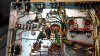
Been a couple weeks but work has been busy and this is the first chance I've had to add to this thread. Cathode and screen resistors installed using some solid copper from stray piece of romex:
IMG_20201029_061420332.jpg

I didn't really like putting the cathode resistor buss underneath the wires and resistors but I thought if I had to replace any caps or resistors in the future, it would be easiest to have them on top rather than have to wrestle with a solid piece of copper wire. I haven't heard any RF or interference with the routing of either set of resistors...so far.

At larryderouin's advice in one of my other threads last year, I replaced a power supply cap repair from some previous owner and put the electrolytic can caps back to original configuration with Hayseed Hamfest capacitors. He also suggested a cap and resistor upgrade/replacement, so they were installed at the same time. Before:

replaced.jpg

After can cap and upgraded parts replacement:

IMG_20201031_183232236.jpg
IMG_20201105_071146543.jpg

So, with all the parts replaced so far and the installation of the cathode and screen resistors, I checked all my work (twice) and hooked it up to my dim bulb tester and variac. Everything looked good, so hooked up a signal and speakers. The unit behaved normally, just like before the work was performed. I compared the pre and post voltage measurements at the power supply, caps and tubes and everything was spot on what's listed on the schematic, maybe a volt or two higher. It was a good morning :) Music sounded great, just as before.

I measured cathode current on the newly installed resistors and found they were close, but not perfect:

V6 - 35.3 mA
V7 - 34.6 mA
V8 - 34.2 mA
V9 - 33.1 mA

Not bad for a fixed cathode bias system, although a clear candidate for an IBAM installation. Pin 2 grid voltages were at 17 volts, schematic calls 18V. I doubt there's any cause for concern with that but I mention it if anyone says otherwise. Heater voltages in line at 6.26V. Plate voltages as follows:

V6 - 372.8V
V7 - 372.6V
V8 - 377.7V
V9 - 376.8V

Anything to be learned from these numbers? Good things or bad? These are 6P14P-EB's from the early 80's most likely. I'm still learning how to assess these measurements and whether the amp is working as expected. It sure sounds good.

The 330K grid control resistors have indeed drifted. Probably still in the 10% tolerance with 349K, 354K, 322K and 329K values for V6 - V9. Also found the 1K resistors connected to the 330K had drifted a little too. Not too bad though, less than 10% as well. Is it worth replacing these? If so, with carbon resistors? Not to open a whole carbon vs. metal film discussion.

I've got more questions about the triac mod and whether or not to do it. A fellow AK'er, K7sparky, pointed out to me the obvious advantage of this particular power switch that, should the primary contacts ever fail due to arcing, the rear extra outlet is connected to another internal switch and could be rewired to function in a pinch. Still, if installing a triac would prolong both sets of contacts then it's something I think worth considering, even with the currently installed CL-80.

I've got a lot of reading to do about IBAM...don't have a clue about what's involved with installing it in this model. I'm hoping to follow Tim D's lead in his X-100-A Long Term Project thread :)

Thanks for reading guys and gals and for your thoughts, opinions and encouragement. Lastly, I gotta give props to my lovely wife for letting me spend so much time hunched over 60 year old electronics. She's a pretty sweet girl for having lost her husband to the addiction. She's already asking when the Fisher will be back in the living room for our nightly listening sessions. The little Kenwood KA-5500 is getting us through, but it's just not the same as the Fisher.

-Steve
 
Last edited:
If I'm reading the schematic correctly BIAS is Cathode based, not fixed. But an IBAM/IBBA can still be installed.
What was your line voltage at the time of your testing, and at that voltage what were the heater voltages on the tubes (measured) V1 thru V3. I know you said 6.26 for heaters but which ones??????

Your tube draw is quite good (within 3-4ma top to bottom). That's considered the max for a normally good spread for non IBAM or IBBA units.

The grid stop resistors (330K) are will within 10%,(=363K) as are the 1K. They can be left alone, but eventually they'll get worse. May take a week or another 10 years. Metal Film is fine, and they don't absorb moisture like carbon comp's.

Listen to SWMBO Steve! She knows quality sound when she hears it. Take too long:whip: and you may find she has found a new spot for the Kenwood, and it'll be quite painful! :rflmao:

SWMBO = She who must be Obeyed......Otherwise known CinCHouse, COMHouseLant, or COMHousePAC (Atlantic or Pacific).
 
Larry,
I'm pretty sure the heater voltages he reported are for the output tubes - rated at 6.3VAC, so those are good measurements.

For the small signal tubes, for the whole string (which includes a resistor too) he's probably going to get in the neighborhood of 30-ish volts. It ends up being less than 10VDC on each tube's heater - which is way low, but that is how these models run. I think if he gets the measurements on the heaters on the 12AX7's in that small signal tube string that we'll confirm all this. The 34-ish ma's that his are running at now are typical but it's running those output tubes hard. That's what Fisher did back then.

Side note: On mine, I am planning on building a separate DC power supply to bring those small signal tube heaters up closer to the 12AX7 spec of 12.6V (or slightly less) on the heaters. That will also free up the bias on the output tubes so that I can drop the overall current draws below 30ma each - because they no longer have to be driven so hard just to heat up those small signal tubes.
 
SWMBO at my home office is also the CEO, Activities Director and in general "The Boss". My SWMBO'd is also a music major and can hear things that I cannot. I value the quality checking that provides. :)
 
Regarding the triac mod, I haven't considered that for any of my projects, but I'll be interested to hear and watch. It may have merit.

Regarding those 330K resistors that are a bit off - I agree with Larry, but I'll add that I sometimes replace them when off that much. Your choice.

Good that you are planning the IBAM/IBBA thing. That will allow you to balance a bit closer on those tubes, but they are "close enough" for my tastes right now. Note that the Fisher design as it is won't allow you to drop the current draws much because the small signal tube heaters that are driven by that same current are already too low (by Fisher design).
 
Thanks for the information Larry and Tim! SWMBO... that's awesome

As for the heater voltages, I was being impatient and just took that measurement from the transformer but I'll get them off V1 - V3 when I get home tonight. Line voltage at the time was 121 but after the thermistor had dropped to 118vac. I've seen my house voltage drop as low as 115 and run as high as 123... makes me want to always have the variac inline. Thank goodness for kill-a-watt meters!

Thanks for bringing up the heater voltages guys. It made me see an understand the circuit more accurately and I now see how it's a cathode based bias and the interaction of those resistor values and how it all plays with the design. It does make me wonder why Fisher chose to run the output tubes so hard instead of a different heater supply but I'm sure cost and tube availability being plentiful back then, yada yada..

I'll be back this evening with those heater voltages and, I'm sure a couple more questions!

-Steve

Oh, and can't agree with you more, Tim, about our better halves and their great hearing. My wife is the definitive reference when listening to new gear or any project I've worked on!
 
Last edited:
The small signal tube heater design for the Fisher X-100-2 and many other Fisher and some competitor amps used that trick to cut parts costs to supply the DC heaters for some of the small signal tubes. That avoided Fisher (and others) from adding in an additional DC power supply for (mostly) preamp tubes. (Notice the "DC". It is quieter than "AC" and that can have a big impact on the noise introduced in the preamplifier stages.) The compromise though was a balancing act between suppling enough current to run those heaters but not any more than that because that current "cooks" the output tubes.

It's sort of ok to leave it that way, but by cooking those output tubes you may end up replacing them sooner then you may want. It's hard to predict how much sooner, but back when Fisher did this - tubes were cheap and plentiful.

(I learned all of this mostly from Dave G's threads.)
 
Okay, got those heater voltages. After a 10 minute warmup:

V1 - 8.81 vdc
V2 - 8.55 vdc
V3 - 8.99 vdc

About what you thought, Tim? I hope I didn't do something stupid. Due to a less than optimal bench setup, I forgot to hook up a speaker/load to the right channel. Not sure if Fishers have the same protection as my Scott LK-72 but I thought I read that not having a load is a no-no. Could someone explain and/or alleviate my concern that I may have done something to hurt the amp?

For good measure, I went back and checked those voltages again with both channels hooked up to a load and got similar results. Also ran some Till Bronner through the amp just to make sure things were still happy :) So hopefully no harm no foul.

Could someone explain the purpose of those phase inverter pots and why I get a foreboding intuition that I should NOT adjust, touch or even look at them cross-eyed?

Anyone have a parts list for IBAM or a favorite thread I could start building my next shopping list with? Tim, were you planning on etching a PCB? I've never done that before but I've wondered if it would make any sense to make a few extras in case a fellow AK member would be willing to pay for such a convenient solution ;)

Thanks again folks! Hope everyone has a great weekend!

-Steve
 
Back
Top Bottom