• The move to the new server is done. There are some software and database maintenance updates in process. This has us passing the hat around to help out. We appreciate any donations. Seriously, even a dollar helps. The payment page may be found here - https://www.audiokarma.org/support.html

Fisher X-101-D power transformer with extra wires

Vintageaudio123

AK Tropicalized Member
I have been slowly collecting iron for an upcoming amplifier build, ideally with 7591s. First ended up purchasing a NOS Thordarson-Meissner 22R07 transformer, HV is around 750V 200mA with center tap, plus one each 5V and 6.3V windings. Then came across someone selling a pair of X-101-D output transformers which I also managed to secure. That got me into thinking of trying to find an X-101-D power transformer to match the set, and recently also got it (which has PN TY113C115 printed on it). The X-101-D service manual that I got (for serial numbers from 10001 to 19999 inclusive) lists the power transformer as PN T1113-115 so at first glace it seems to be a numbers match.

However this power transformer has 3 secondaries whereas the X101D schematic only shows two secondaries (HV and 6.3V windings). My transformer has an additional 3 wires (green-black, red-black, and white (or tan)-black. The HV and 6.3V windings where easy to check and identify: red with red-yellow is HV, and green with yellow is 6.3V. And the primary wires are black with black-white.

On this additional 3-wire secondary I was able to measure 122.4V between red-black (which seems to be the center tap) and green-black, and 140V between red-black and white-black. Furthermore, when I measured between the green-black and white-black which would be the two ends of the winding I only got about 20V, or about the difference between the two previous half-winding measurements. So it seems that these two half windings strangely seem to be out of phase with each other and bucking the total voltage. There is no continuity between any of these wires with any of the other secondaries, only among themselves.

Anyone know what this additional winding not shown on the schematic might be used for? The X-101-D does not use a separate winding for the bias supply, so wondering if someone could tell me why this transformer might have this extra winding. I also checked the schematics of the X-202 series, the 500C and 800B, but none seems to match this transformer I've got.
 
Last edited:
Register to hide this ad
International version. Extra primary that goes in series or parallel with other primary. If the the other windings measured 20% high, it's 100V (used in parallel for Japan) and the 20V section goes in series for 120V (or 220V). If other voltages are close, then it's two 115V windings, giving 230V in series (250V at the extra tap).
 
Are you positive on this? I cannot understand how the regular two wire primary (between black and black/white) can be wired into those three additional wires. Any chance you could elaborate a bit further, or perhaps point me to a schematic that shows the hookup for the international version?

And by the way the secondary voltages seemed to be on spec, slightly high as expected for an unloaded winding.

In any event the transformer draws about 170mA from 120VAC while unloaded, which seems pretty standard for these type, as (the Thordarson 22R07 draws about 190mA unloaded) so it seems like the hookup to just the regular primary would be about right for it.

Thank you.
 
Last edited:
normally with dual voltage primaries you get a pair of 120v windings. They wire in parallel for 120v operation or in series for 240v operation. It will work if only one primary is connected but its good for about 1/2 the current.

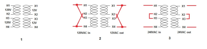
This for example, different sort of transformer but the primary side is the same idea

1744633040001.png

with this one the extra set may be 0, 100, and 120v so it can be used in Japan on 100v mains. 0v on both wire together, 120v on both wire together, and mains is fed between 0 and 100v for that setup.
 
Hi, yes that standard 2 primary 4-wire multi voltage winding scheme I fully understand and have seen many times. But again in this case given this extra winding is 3 wires and the regular primary has two, still not sure how that would tie together.

Also weird that that winding from the center tap to one end measures 120V, and 140V to the other end. But if I then measure end to end (without the center tap) I only get 20V, like both windings are out of phase and bucking each other.

I confirmed that center tap (red-black) as measuring resistance from it to either side (green-black and white-black) shows about 4-5 ohms, but if I measure end to end resistance it basically measures less than one ohm, almost as it where shorted, which obviously is not the case.
 
maybe @RS Steve knows. I believe he's got a couple of 1800's, which is the multi-volt version of the 800C. I'd take a wild stab and say its going to be similar, even if its not the same transformer exactly.

but I suspect its still going to be like wiring the 120/240v setup just with one extra lead that doesn't get used. That extra lead is probably a tap on a 120v primary so it can be used on 100 volts.
 
This is the only way I could figure this extra primary to help with compatibility with other primary voltages, but still not sure.

In any event if this would be the case, and since I would use 120V mains seems I would not need to bother with the other primary... or is there anything else involved.
 

Attachments

  • VOLT-SEL.jpg
    VOLT-SEL.jpg
    56.5 KB · Views: 9
Last edited:
If you're getting 20v from white/black to green/black it means the red/black isn't between them. Red/black is probably at the bottom, green/black is the tap, white/black is the other end of the winding

not sure on the phasing but taking a guess here, for 120 operation you probably need to tie the black/white to the white/black and the black to the red/black.

if that tries to draw a lot of current, flip the white/black and red/black. If the phase is reversed it will act basically like a dead short so it will be pretty obvious even at low voltage.
 
I assume that red-black would be the center tap since resistance readings to each of the other two wires are about equal at 4 and 4.5 ohms each for the green-black and white black wires respectively. I think the 20V are happening because the 120V and 140V windings being in series but also in opposite phase (maybe wound the other way onto the core) so this may be why they are bucking each others voltage and the end result is the difference voltage between both. Its the only explanation I can come up with, however not sure if that would also account for the almost zero ohms resistance reading between these two outer wires without connecting anything to the red-black. There can definitely not be a short between them as otherwise I would not be getting the 120V and 140V individual readings to start with. Aside from that the transformer does not get hot at all, just pulling 170mA at idle without any secondary loads. If there where a real short in any winding that current reading would be much higher due to the low impedance reflecting back.

BTW was checking the AK database and looking at some of the Fisher X101 series power supply schematics and they all are 105-120V only, none has a way to select mains input voltage, at least not on the schematic. Also noticed that for the X-101-A variant there was only a user manual available, and I do have a schematic for this model which I wanted to upload, but could not find a way to send the file. What would be the procedure to contribute this file?
 
I agree - the extra winding is 120V with the blk-wht wire adding another 20V (sleeve that wire and forget it). I recall seeing a 140V tap on a 1930s export radio, but don't think that voltage was used anywhere on the planet by the 1960s. Bucking 120V as shown wouldn't be done as it would be very inefficient - transformer would have to be considerably larger. If the small section were opposite polarity (for bucking 20V) you would have read 100V. But a 100V tap on the winding could do the same with less copper.
 
I went to look for under chassis pictures of X-101-Ds and most are for domestic 105-115V only units that the transformer wiring seems to match the one on the schematic. But I eventually came across one (unfortunately not very good) picture from a french forum which seems to show some additional transformer wires tied onto that 6-contact terminal strip that is right next to where the transformer wires pass into the chassis, and what looks like a configuration jumper between two of the strip contacts. Unfortunately this last picture was neither very big in size or good resultion, so not really too much useful information that come from it. In contrast all the US versions only seem to have any connection to the two right most contacts of that terminal strip, and there are no visible jumper wires between any other contacts.

However the ebay seller that sold me the transformer still has the amplifier chassis and so far only managed to send me a partial picture of the terminal strip, which seems to somewhat match what the picture from the french forum shows. I asked the seller to send me a better more complete and detailed picture of that area and are waiting to hopefully receive it soon, but it has already been a few days so far. This picture also seems to show the small wire stumps left behind after the cuts, but are probably too short to make much difference, and at least two jumper wires between contacts.

Here is a comparison of the two "better" pictures I found online, again unfortunately not taken in the same angle or even orientation, so had to do some image editing to make them a bit more similar. Also separately posted the picture that I have so far gotten from the chassis where the transformer actually came from.
 

Attachments

  • X101D Transformer Wiring Comparison.jpg
    X101D Transformer Wiring Comparison.jpg
    49.5 KB · Views: 7
  • X101D TRANSF TERMINAL STRIP.jpg
    X101D TRANSF TERMINAL STRIP.jpg
    97.7 KB · Views: 4
That is the one transformer I found, and was just trying to figure out what the extra 3 wires that are not shown on the schematic where for. This has led me down this rabbit hole of the international version equipment, which I did mostly out of curiosity as really only need to use it on 120V primary mains. But on the other hand also wanted to make sure I understood what the extra wires do, not to leave out something that might be needed even with a 120V primary application.
 
In addition to getting a better pic from the seller, the chassis should be marked as to the AC line voltage. If it's an overseas model, at least you'll know for sure why the xfmr has additional wires.

Jack
 
Back
Top Bottom