• The move to the new server is done. There are some software and database maintenance updates in process. This has us passing the hat around to help out. We appreciate any donations. Seriously, even a dollar helps. The payment page may be found here - https://www.audiokarma.org/support.html

Fisher X-19 Cap ID

Oerets

AK Subscriber
Subscriber
In the hopes of retrieving from the dead a X-19 Integrated Amp I have stumbled upon.

The cap ID in SM as a C2 electrolytic 100uf 250V but on schematic not shown as being polarized. Plus on the caps bottom there are two red wires connected and one black in use.

My take on the way to install the new cap is the positive lead to the feed CR2/R3 and run a feed to the tuner supply J10/300V . The negative side to C3.


Any thoughts or help with this will be much welcomed.


Barney
http://file:///C:/Users/Barney/Downloads/X-19 2A.pdf
http://fisherconsoles.com/service manuals/allegro a9 a19 sm.pdf
 
Last edited:
Register to hide this ad
Barney; C2 is the ISOLATED Can cap with the Cardboard cover. It's IS polarized but is Not grounded to the chassis and will have up to 300v on the case. It daisy chains (in series ) with the C3A section to become the Voltage Doubler. C3A neg is grounded, then c3A POS ties to the C2 NEG (case) and the one side of T-1. C2 Positive ties to CR2/R-3 and feeds to The J-10 connector and also the "A" (A inside a triangle is the "A" feed to the center tap of the output transformers) ties.

C-2 will have a phenolic wafer between it and the chassis Make sure there is absolutely NO CONTINUITY between the chassis and that can, period. If there is when you put power to it, there will be fireworks. Cover it with tape if it has no insulation on it. I take it that the CAN CAP you are referring to in POST #1 is a replacement like an FT dual cap? Take a couple of pics, just so everyone is on the same page. I think I'm with you but not 100% sure.


In essense what you are thinking about is making that cap,(it sounds like a FT 2 section cap with dual leads making it 2 sections) 2A and 2B which won't work. 2A connected to CR2/R3 and 2B connected to the J10 separately. 2A will have the correct voltage all the way down the line, but 2B will not as it's not connected to the CR2/R3 junction. Keep the Voltage Doubler balanced and cap off one of the RED's and isolate the lead out of the way, and just use the other red and black.

BLACK to the Junction of C3A and T1 lead.
RED to the CR2/R3/J10 lead.

Please take a picture of the cap from Post #1 and post. If needed then I can make adjustments in this post. But this isi what I get from your post.
 
I do not have a cap yet to replace the old cardboard one. Was hoping to use a 100uf axial mounted under the old one.

Going to take better pictures now.


Barney
 
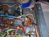
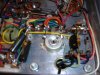
OK, here a new pictures of the old cap and wires.

Also supplied a picture of the supply feed to transformer. Show I replace the caps with a new safety cap?


Barney
 

Attachments

  • Cap pic 1A.JPG
    Cap pic 1A.JPG
    102.9 KB · Views: 13
  • DSCN6948.JPG
    DSCN6948.JPG
    80.4 KB · Views: 13
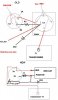
Based on the schematic here's what I came up with, both as is now, and after you replace with 100uf 300v cap. Use a TERMINAL STRIP to mount it DO NOT USE the CENTER (grounding) lug. And make sure that any bare areas on the cap are taped good. You don't want to brush up against it and get a BIG JOLT!

replace R3, and CR2 & CR1 with UF4007's. C1 gets replaced with a Safety cap yes.

The description of the wiring is what threw me off initially. You said 2 reds and a black and I presumed a FT Dual Cap. It's all good now.

Just follow the diagram and you'll be good to go.
A-19 cap diagram..JPG
 
Thanks, looks like what I was hoping for. To late tonight to think more on this, got a early start and a long day ahead.


Barney
 
PM replied to; I'm pretty sure that the C2 or C3 cap is shorted if it blew the diode with the new cap attached to C2. Try it without the extra cap bridging C2. If the diode blows C2 or one of the C3 sections is shorted. The new cap looks like it was wired correctly.
 
Last edited:
Replaced the diode and all of the leads removed from old paper cap. Had left the diode and wires connected before separated from old cap the two wires that went to the neg side of new cap. Checked with meter and it showed open and thought it would be OK. Guess not.

Powers up dim on DBT but no sound. No power to tuner unit. Feed from J10 IIRC. So will order the caps need for the other electro can C3 and test then. High voltage caps I don't normally stock. Plus check tubes too!


Thanks.


Barney
 
Normally I get can cap replacements 50v higher than spec'ed. Give's you a bit of headroom in case the working voltage is real close to the caps max (<20v max difference). In this case your max B+ is in the neighborhood of 300 so the 350's should be ok even with the higher wall voltages.
 
I was hoping to clean out the old paper one and insert a radial. On the metal can ones still checking sizes and options.

Got Grand Kids (twin 3 year old boys) for the next few days.So will be busy doing more important things.


Barney
 
Nichicon UCS series about the thinnest one's. You might be able to squeeze the 100uf/40uf/20uf sections in the one can (c3) but not the 220uf. Hayseed would be an option if there isn't room to mount a couple of terminal strips and run them that way.
47uf 350V 647-UCS2V470MHD
22uf 350v 647-UCS2V220MHD
220uf 350v 647-UPW2V221MRD (220uf 350v not manufactured in UCS)
100uf 350v 647-UCS2V101MHD (250V out of stock on order ). Use the 350V in both C2 and C3.
 
GAWD! I sure don't envy you. I'm glad I can tell my grands apart (5year old girl and 3 year old boy).
 
Not to had to tell apart, Fraternal and the older is close to 10 pounds heavier.

No nap so far, watching Thomas the Train right now.

Great times ahead for the both of us AK Grand Dads!


Barney
 
Last edited:
I take my grandson over to the park across the road just off the end of runway 33L @ BWI in Baltimore 2-3 times a week. Sit there for a couple hours, watch the planes land(80% of the time) or take off, and hit the playground. Mainly 737's with the occasional MD-80 (DC-9) and short bodied 747's. 150-200ft agl by the time they go past us at the park when they land. about 500ft taking off . viewing area is about 500ft off the flight path, and it can get a bit loud when the big guys come in. But not as loud as a Connie with all 4 of those P&W R-3350's poppin and spittin as they run the throttles up and down. Take off's are a different thing. Good thing I have a couple pair of flight deck cranials (OLD!) from Navy Days. Oh for the days of Tomcats in zone 5 burner on the flightdeck getting a cat shot. Hell, I'd settle for a Phantom shot.
 
Miss the ramp and being around the aircraft, Main Line commercial for me. Nothing like the smell of Kerosene and coffee at 0500 to start the day.

My Son, Sister, Father, and Mother were the ones in the Navy. Not me never got the letter and my lottery number was three for the draft too. My son was on the Nimitz for a couple of cruises.


Barney
 
Back
Top Bottom