• The move to the new server is done. There are some software and database maintenance updates in process. This has us passing the hat around to help out. We appreciate any donations. Seriously, even a dollar helps. The payment page may be found here - https://www.audiokarma.org/support.html

Fisher X-202 - Bias & DC Balance settings using tool?

ssouci

Well-Known Member
I have a newly-acquired Fisher X-202 amplifier (not X-202-B)

I want to check and adjust the Bias and DC Balance settings, but notice that the official Fisher method requires desoldering a jumper and taking reading from beneath the chassis, something I find to be a real PITA and would rather avoid

so, I bought myself a "Bias Adjusting Tool" (bias probe) on eBay, a simple yet clever device which seems like it would be very handy, and hopefully I can use it with the X-202?

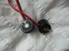
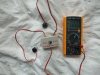
the tool consists of 2 tube socket adapters (to enable simultaneous testing of both tubes in a push-pull pair), an A/B switch box, and leads that plug into a multimeter... SEE PHOTO

the tube socket adapters are plugged into the amp, then the tubes are in turn plugged into the adapters... this allows cathode bias current readings to easily and safely be taken from the appropriate pins while the amp is running

the probe cables are built with a 1ohm 1% 1W metal film precision shunt resistor in the socket for the path of the cathode current flow, and by using Ohm's Law, the observed reading in mV equates directly to what the current is in mA (eg. reading of 45mV = 45mA cathode current)

by flipping the switch back & forth, comparative readings of tube A and B can be easily obtained (without disturbing anything).... I guess this helps set the balance?

QUESTIONS:
1. can someone provide step-by-step instructions of how to use this tool to set the Bias? (hopefully without touching the internal jumper wires)
2. what cathode current should I be aiming for?
3. can this tool also be used to set the DC Balance, or will I still have to use the normal method (and desolder the jumper)?.. if it can be used, how?

apparently, when using this tool, I should set the bias current for "the appropriate range for the tubes in use", but I'm not sure of exactly what that is for these tubes, and/or for use in this particular amp... also, I hear that people often set the bias "approximately 10% cooler/lower than spec" to compensate for today's higher wall voltages, or maybe to affect the sound?... I want to optimize for the best sound, even if it costs me in tube lifespan

this amp specifies 7189 output tubes, but I am using new-manufacture Russian Sovtek EL84M tubes... they are supposed to be a very good 7189 substitute (although I'm skeptical)... I want to initially try out the tool on these

I've also ordered and awaiting some OLD-manufacture Russian 6P14P-ER tubes made by Reflector Corp (Saratov, Russia), which some claim sound better than the new EL84M, even though "they are essentially the same tube"... btw, also wondering if these would require a different bias setting?

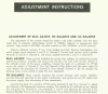
I've attached a copy of the official Fisher bias setting method as reference... SEE PHOTO

my wall voltage is ~118VAC, and Fisher says to use 117VAC for taking readings, so I am OK there

any help or feedback greatly appreciated, thank you!

PHOTOS:
- bias adjuster tool (hooked up to multimeter)
- official Fisher bias setting instructions
 

Attachments
  • DSCF0681.JPG
    DSCF0681.JPG
    76.7 KB · Views: 53
  • fisher_bias_dc_adjust.png
    fisher_bias_dc_adjust.png
    507.2 KB · Views: 51
  • DSCF0682.JPG
    DSCF0682.JPG
    76.1 KB · Views: 50
Last edited:
Register to hide this ad
All it does is give you the readings from a position that is a little safer, but you still have to get underneath it to make the adjustments. Same thing as taking voltage readings from the top and adjusting underneath by lifing the tube slightly on the pins and touching them with the probes. A lot safer too.

El-84/7189 types are 12W tubes (according to the RCA tube manual.) 70% to 80% of plate dissipation (12W maximum) is between 8.4W and 9.6W. The EL-84M and 6P14P-EV are essentially the same tube. And both are very good tubes, both physically and sound wise. They will sound pretty much the same. Not exactly but about 95% same. You still have to use the FISHER manual instructions but with the bias adjustment tool (should be bias indication tool) you won't have to stick your meter probes all over the place.

It won't indicate Tube balance, which means you still have to get underneath to measure and adjust.

Don't obcess over 1 volt of wall voltage. it won't make that much difference if any. The 117V spec on there is Fisher's spec for designing the circuits. It's designed to run from 105V to 120V with no problems.

As for what cathode current you should be looking for, can't help you there. Suggest you keep an eye on the V1 thru V6 heater voltages as they are part of the bias circuit.

I would use the tool to get the initial readings and follow the FISHER instructions with suitable modifications by Dave G.
 
thanks Larry

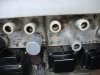
my unit has the adjusters on the top-side, as per attached photo below... so I can do all adjustments from there, can't I?
 

Attachments

  • DSCF0171.JPG
    DSCF0171.JPG
    71.9 KB · Views: 42
exactly. You'll still need a VTVM and to disconnect the jumper as noted in the instructions. Use the "special tool" to note the voltage at the tube after going thru the procedure, as a 2nd verification check.
 
UH-OH, SO NOW I REALLY NEED HELP !!!

first, thing I did was use the measuring tool to see where things stand BEFORE I touched anything

(again, this amp was running well and sounded good, but I want to make sure the bias is set correctly, and I want to learn how to do it for when I get some different output tubes)

tubes are Sovetek EL84M, matched quad (apparently from J. McShane)

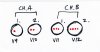
here's a diagram of the 4 output tubes, as seen from above looking from the front... I marked each tube with red dots (*) to identify them:

IMG_20160821_0001.jpg

I turned everything "off", volume set to zero, and left the speakers connected (8 ohms)... these are the readings I got in mV (directly equivalent to mA):

20.1 / 28.4 --- 26.3 / 25.7

so, channel B pair looked pretty close, I think within a reasonable range from each other?

however, channel A pair looked to be pretty far apart, I assume too far apart?

so, looked like the channel A tubes perhaps were not well matched after all... so I swapped those two tubes (* and **) to see what would happen... surprisingly, the low reading stayed in the #1 position, and the high reading stayed in #2 position, so the difference in readings appears to be caused by the tube position/socket, and NOT the tubes themselves

then, with the tool in place, I tried turning the Bias adjustment pot, and sure enough, the readings went up/down as expected, so I don't see why I can't use this tool to adjust the bias more easily from the topside (without having to open the chassis and desolder the jumper, and take readings across the resistor located underneath, but that's another story...)

I then used the tool to set the outputs to an average figure of 25 mV as best I could to even the channels up... had to go to a compromise midpoint for channel A, because they were so far apart

so, the next step was to open her up and see if I could spot anything, and also to perform the correct Fisher bias setting procedure...

first I took some voltage readings at various points just as info gathering:

402 / 402 / 403 / 402 < VDC pin 7
301 302 / 302 / 302 < VDC pin 9
-12.4 / -12.2 / -12.1 / -13.1 < VDC pin 2
423 VDC < rectifier tube pin 8

to be continued...
 
Last edited:
then tried to perform the correct Fisher Bias setting procedure...

fisher_bias_dc_adjust.png

procedure says to remove loudspeakers and connect load resistors across the terminals, and to use the 16 ohm terminals and to set the speaker jumper to 16 ohms... I did NOT do this, and instead left everything as-was and left my 8 ohm speakers connected... looking back, not sure if this was a mistake?

I desoldered the jumper wires and took readings across the bias measuring resistors as per instructions and got:

0.472 / 0.390 < VDC across bias measuring" resistors for channels A / B respectively

the spec says set to 0.6 VDC, so I adjusted the bias pot to increase both channels get exactly 0.6 VDC... I had to back & forth a few times between channels to get them to both match and stabilize

out of curiosity, I flipped it over and took readings of the current with the bias tool, and got approx. 30 mV (ie., mA) in cannel B, so the increase in bias was being reflected as expected

I also took a few other readings for info:

.604 / .607 / .624 / .622 < VDC pin3 (with jumper desoldered)
11.8 / 11.5 < ohms, resistance of the 10 ohm "bias measuring" resistors

so great I thought, this is going well...

next, I tried setting the DC Balance, so I left the jumper desoldered

procedure said to hook up a meter across the speaker terminals, and I was not sure if the speakers should be left connected... I decided to leave them connected to take my readings.. again, I used the 8 ohm terminals and speaker jumper (not the 16 ohm that Fisher specified)

the meter gave very low readings (in mV) as I expected, but they moved around a lot and went +/- around zero, and were unstable... in the end I don't feel like I could even take a proper reading... moving the DC Balance adjustment pot around seemed to have little effect, so I set it back to approx. where it had been... then I aborted this test... I figured I could not get a proper reading either because I'm using the wrong kind of meter, or because I had left the speakers connected... this is still TBD

then I resoldered the jumper, and flipped it over, and thought I'd take another set of readings on the topside using the bias tool to double-check and see where things stood... I put the tool on channel A this time, let it power up, then noticed I was getting weird readings, and that one tube (position 2) was going up and up higher... I then noticed with great alarm that both the channel A tubes were REDPLATING even though my room was bright, so I quickly shut off the unit... in my panic, I did not have a chance to see if the channel B tubes were also redplating

YIKES!!!

in the end, I did not actually change anything -- except for increasing the bias level... I checked underneath and it does not appear that I shorted out or disturbed any wires while adjusting the bias

my confidence is a bit shaken, so now what... what's the best way to proceed?

the most pressing questions:
- why did I get redplating?
- was my bias adjustment method incorrect (and was using 8 ohms a mistake)?
- why are the two tube positions in channel A giving current readings that are so far apart?
- why didn't my DC Balance test work?

sigh...

REF: schematic of output tube area:

fisherx202_outputs_schem_v2_2016-08-19_1546.png


REF: speaker connection info (most confusing speaker terminals in the history of audio!):
x202 speaker terminals.jpg
 
I just tested ALL the tubes in the amp...

all are "good", including the 4 output tubes which measured in the good zone with readings pretty close together... no shorts detected
 
S -- You didn't do anything particularly wrong. Comments include:

1. Don't get caught up in the 8 or 16 Ohm, speaker or load resistor issue. The point is to get some kind of proper load on the amplifier to help steady out the readings which, when any little disturbance comes along, would be more exaggerated without the load connected. Just make sure the volume is turned full down, and there is a speaker or resistive load of the correct value connected to whatever tap that load represents.

2. There will be fluctuations in setting these controls even when you're not adjusting anything. Small AC power disturbances will always make for a blip in a given reading.

3. You are using a very sensitive DVM, which is something that Fisher engineers could only dream about using back in the day. It can look like it is moving all over the place, where an equivalent analog meter would hardly show any movement at all.

4. There is no reason that you can't use your tool to measure output tube current flow. No doubt that the internal dropping resistor within the tool to allow for the adjustment is much more accurate than the ceramic power resistor that Fisher chose to use for that purpose. Trying to get a reading from your tool to match that produced by the internal resistor is much like the poor fellow in the watch repair shop trying to get all of the clocks in the shop to chime at exactly the same time.......

5. As for the red plating, examine the pins of your tool closely, and particularly that of pin #2. Often, the pins on new manufactured 9 pin tubes and devices are slightly smaller than those manufactured from back in the heyday of the tube era. It is not uncommon to find that modern devices don't make as dependable a contact in yesterday's tube sockets due to the socket receptors being sized/stretched to receive the older pin size, versus the size of the pins on the modern tube/device. If your unit was not red plating before, then the possibility of poor pin contact to the amplifier's socket (or to the tool's socket if you are using modern tubes) is a good possibility. Also consider the possibility that if you are not particularly familiar with the bias/balance adjustment procedure, that maybe you were simply adjusting the wrong control versus what your meter was connected to measure. It happens.

6. In the end, both the cumbersome and poor accuracy Fisher method, and having to remove tubes to install tools for measurement is a pain either way you go, although the latter method is preferable in every way to the former. Ultimately however, I would consider the modification I documented in my X-202 thread, where in the two speaker terminals in each channel that are used to facilitate the antiquated damping control feature found on this amplifier are freed of their internal connections (the damping control circuitry is removed, as it is an anachronism), and the four free terminals created are then used as test points tied to each cathode terminal. This, along with the installation of individual internal 10 Ohm 1/4 watt cathode sampling resistors (the original 10 Ohm ceramic resistors and shorting wires are permanently removed), then completes the modification. This then puts the entire issue to rest, as then you can check the current flow of any of the four tubes at any time at will, to monitor the various settings or drifting of different tubes, etc.

Again, your basic approach is correct. Barring that nothing is wrong with your amplifier or tools, you should be able to get all four of your output tube quiescent current readings to match very closely using the measuring tool you obtained for that purpose. I'm just giving you some points to consider along the way.

Good luck with it!

Dave
 
Dave, thanks for the reply!

- what's your guess as to why for channel A, I observed such different readings for the current flow in the 2 tubes... since swapping the tubes also swapped to high/low readings, I can only assume that the circuit itself is causing the difference, not the tubes themselves... what's the most critical thing to check or test and how?

- can you pls. point me to your thread documenting the "independent tube bias mod"... that sounds like a very good idea

thanks!
 
thanks Dave... I never got to that point, because when I hooked up the meter to the speaker terminals (to perform the DC Balance setting), the readings I got were unstable and very small, and moving +/- from zero... since I was not sure if I should have the meter hooked up with the speakers still hooked up (which I did) or not (Fisher did not specify if speakers or load resistor should be left on or off) I was very unsure of this test... that's when I flipped the unit over and noticed the redplating, so everything was stopped there

excuse my ignorance, but does the DC Balance pot then control the relative currents within a tube pair?... does that mean I could instead set the DC Balance by simply hooking up my bias probe tool (one probe on each tube in a pair), and then adjusting the DC Balance pot for the most equal current between the two?
 
The beauty of the Bias Control and DC Balance Control arrangement is that you connect your dvm between the cathode test points of the two tubes in a given channel (you would use a tool for each tube in a pair), and then adjust the DC Balance control for a 0.00 vdc reading between the two tubes. This is because, if the two tubes are drawing the same identical current, then there is the same identical voltage drop across the internal measurement resistor within the two probe tools. So if your meter is connected between the two tools, then a balanced condition will be achieved when the voltage indication is 0V. Once that condition is achieved, then connect your meter between either probe tool and ground, and adjust the Bias control for the proper reading (30 ma in this case). The Bias control will raise or lower both tubes equally (maintaining the balance), which simplifies the adjustment process. The controls do interact somewhat, so once one is adjusted, go back and check the other until both DC Balance and Bias indications are on target.

I hope this helps!

Dave
 
Back
Top Bottom