Anatomy of a Modification:
Mopping Up
Details, details. Some related to the modification, some not, but all relevant to the SA-300.
1.
RFI: Fisher clearly saw the SA-300 as providing monitor service in recording studios and radio stations, where RFI would run rampant. This is evident by the inclusion of C16, C18, C29, C30, C37, C39, C50,and C51 -- all designed to prevent the entrance of any RF energy inside the chassis. Unless you're living within a few miles of a commercial transmitter, these take up space and clutter the build. In the modified amplifier, they have all been removed.
2.
Filtered and Unfiltered Inputs: In the original SA-300, the Filtered input provided both a high pass and low pass filter circuit that the input signal first passed through. This was stated as benefiting performance when using the amplifier with (the then new at the time) electrostatic speaker panels. Whether that's the case or not, Fisher promptly dumped the high pass portion of the filter circuit in the SA-300B, leaving only the low pass filter, so that only supersonic frequencies would be rolled off. The only other change made to the B models was the addition of a center channel output jack.
In the modified amplifier, all the original filter components have been removed, and I use the Filtered Input Jacks for a more practical purpose. The modified amplifier retains the original sensitivity of the stock design (0.90 vac rms for maximum power output), as appears at the Unfiltered Input Jack. However, this is frankly a little too sensitive for use with a typical active preamp, and certainly the 400CX-2 with which it was paired in the President console. That meant that the level controls had to be backed down, but as is so often the case, that compromises HF transient performance in the process. Accordingly, the Filtered input on the modified amplifier is now a fixed level, compensated input, requiring 1.53 vac rms to achieve maximum power output. In this way, response is not compromised, and the sensitivity of the amplifier is much more appropriate for use with the active preamp of your choice.
3.
Output Tube Drive: Between the increased bias voltage the relaxed quiescent current draw requires, and the NFB provided from the partially cathode coupled configuration, the modified output stage requires basically twice the drive level that the stock output stage does, something that the stock phase inverter/driver stage was nowhere near capable of delivering, as it struggled just to deliver even that required by the stock output stage, where at 20 Hz, it basically ran out of steam before full power output was even reached. A significant portion of the success of the modified amplifier, is due to the fact that the phase inverter stage was able to be modified to provide plenty of increased low distortion drive to the output tube grids, across the full 20 Hz to 20 kHz spectrum, at full power output with both channels driven, with even a 10% reserve of drive capability remaining at 20 Hz to account for tube aging. Overall, the inverter stage becomes a much more stout driver, which is just the ticket needed for the increased drive requirements of the modified output stage. The increased drive was accomplished by raising the values of R21&R47, and R22&R48 to 43K@ 2W and 51K@2W respectively, removing and shorting out R24 and R50 (eliminating C31 as well), and replacing R64 with a 20 Hy, 20 mA Hammond choke. Finally, C23 and C44 are increased from 0.1 uF to 0.22 uF as well. Collectively, these changes allow the original 12AU7 phase inverter stage to provide all the drive necessary for the modified design. In the process, the B+ supplied to the inverter stage is not only appropriately elevated, but also filtered much more effectively as well.
Regarding the (now defunct) AC Balance Switch: The loss of this feature is not as great a loss as it might seem, as being a low level adjustment, it cannot provide for a balance adjustment made under Class B conditions, where AC balance is needed the most. As a result, the setting achieved by adjustment for minimum noise in the output rarely coincides with that produced by adjusting for minimum THD at higher power levels, which is how such adjustments are typically made. This is not to poo-poo the original scheme used, but simply to say that it's only accurate if tightly matched output tubes and phase inverter tube sections are employed. I removed the feature to maximize phase inverter/driver tube peak output capability.
4.
AF Amplifier Stage: I recommend disconnecting the level controls and leaving them in place as dummy pieces. Or, if yours are sufficiently matched, then the new attenuation networks for the Filtered Inputs can still be used in conjunction with the controls, but usually, they will be insufficiently matched to allow for this. Of my controls, one measured 248K, and the other 143K. At this point, any controls I've found as suitable replacements require the mount hole to be ever so slightly enlarged, which I have resisted doing, since I don't like using level controls in the first place. If you (electrically) remove the controls, then replace them with matched 270K resistors, which will then allow the Filtered Input Jack attenuation networks to operate with a tight match as well.
Because the global NFB is now effectively being sourced from a 4Ω tap (1/2 of the original 16Ω winding used), the NFB network needs to be adjusted to maintain the same feedback factor as the original network did before the new output stage short loop was added. The new NFB network then should consist of a 3.6K resistor, and 270p cap. C28 and C49 are no longer used.
The original input grid components R12, R38, C14, C15, C35, and C36 should all be removed, and a 75K resistor connected between the input grid, and either the wiper of the level control (if retained), or the tip of the Unfiltered Input jack, where a 270K resistor to ground would also reside. If the attenuation network is desired, connect a 180K resistor in parallel with a 72 pF cap between the Filtered and Unfiltered Input Jacks.
At each 290 volt source, connect a 470K 0.5 watt resistor to ground, this to account for the higher B+ serving the phase inverter/driver stage now. These resistors also act as absolute bleeders, and are quite effective in regulating the 290 volt sources in the face of large changes in B+ voltage.
The step networks consisting of R19, R20, R45, R46, C20, C21, C41, and C42 should all be removed. They are not replaced with anything. The components of the series step networks (R17, R43, C19, C40) should remain in place as originally installed.
Odds 'n Ends:
1. The heater leads to V5 are usually not twisted. With the modification in place, these leads should be twisted to eliminate any hum from Channel B.
2. Adjust the Channel A Hum Balance control with the bottom plate in place as much as possible, lifting it on the end of the chassis where the hum control is located just enough to be able to make the adjustment with a long shaft screwdriver. If the control is adjusted without the plate in place, the adjustment made will be inaccurate once the plate is installed.
3. Power Supply Modulation: As full power is approached in both channels, power supply modulation of the output waveform ibecomes significant. This can be all but eliminated by the addition of a 64 uF @500 volt cap connected directly to the output of the rectifier tubes (Pin 8). This will raise the main B+ voltage by about 10 volts or so, which is insignificant compared to the performance improvement provided.
In the last installment, final performance of the modified amplifier will be discussed.
Dave
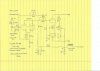
Below: Schematic of the "Front End". This shows the changes discussed in the text. Not shown is the 64 uF cap added to the output of the rectifier tubes.
Below: New Phase Inverter/Driver Stage plate resistors help facilitate the increased output needed to drive the modified output stage.
Below: Channel B Input Stage.

Below: Channel A Input Stage.
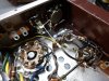
Below: New choke supplying Phase Inverter/Driver and AF Amplifier stages resides where old bias control once lived. Also, the new 64 uF 500 volt cap reduces noise under all conditions, and modulation at near full power conditions. A big benefit of this cap's installation is that now, the two 15Ω power resistors dissipate just 0.5 watt each under quiescent conditions. Along with all the other benefits of the modification then, the amount of heat generated under the hood with the modified amplifier is very small compared to the stock design.
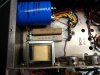
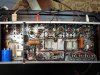
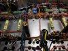
Below: The fully modified amplifier. The underside is now very clean and un-cramped in layout and presentation compared to the original build. Performance results exceed the original design in all performance categories, while the performance quirks of the original design are all gone. The heat output from the amplifier is now quite nominal in routine use.