• The move to the new server is done. There are some software and database maintenance updates in process. This has us passing the hat around to help out. We appreciate any donations. Seriously, even a dollar helps. The payment page may be found here - https://www.audiokarma.org/support.html

Fixing a TX-6500 Tuner - Need some help

jcnash

BUSTED!!
Hi all,

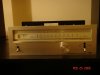
I recently picked up a TX-6500 tuner on one of my trips. I knew that the dial backlight and the power/stereo indicators were out even before buying, but I brought it home and plugged it into my amp hoping atleast for some music, but not a peep.

So ive opened it up and replaced the three lamps which provide the dial backlight and the lamp/led which are the power/stereo indicators, and they work fine.

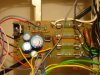
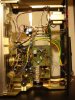
Now for the more important part, I have done some inital analysis on the boards in the tuner. All 4 fuses were tested and are working fine. However, there are three pins on the power board connected by wires to the tuner board. One of these pins has no voltage on it. Im assuming that these three pins supply power to the tuner section, so the fact that one of them has no voltage is concerning.

Ive tried looking for a SM on the Pioneer database to figure out if there should in fact be any volatge on that pin, but no luck finding the TX-6500 SM (Found the TX-6500II SM which has a different pin/board layout).

Any advice/pointers anyone?
 
Register to hide this ad
There is one regulator transistor on that unit also. It makes 13.8 vdc. Verify that it is present. It is probably a d313 transistor. Its emitter should have the voltage and it should be on one of the tuner board posts. Measure for it with the neg lead of your meter clipped to the chassis.
 
You said that the new lamps work. Does the stereo lamp light up? If so, it is odd that you get no sound.
 
Stop fumbling around in the dark, Rick at stereomanuals.com has the tx-6500 manual - he makes high quality paper reproductions @ iiac $15 - $20

I just googled his site specifically (a very quick way to check for a manual) and they do have it.

Four fuses makes me suspicious as to WHAT is really involved in the power supply. The 6500 is old enough that they may have done it old-school without some of the chips we usually see. You haven't had fun until you troubleshoot a L+R / L-R matrix stereo decoder implemented in either individual transistors, or a bunch of transistors on a chip. :D

( what are all those INDUCTORS and TRANSFORMERS !!???!!! :yikes: )

In the meantime:

:worthless:


WHAT are the chipnumbers they used??
 
I've been messing around with a TX-6500 for the past few days. I picked it up with an SA-6500 a couple of years ago and this tuner was thrown in for free. After I got it home I realized why, someone had tightened all the variable capacitor screws and cracked a ferrite adjustment core. It works now but I need to get an FM Multiplex generator to dial in the slightly noisy stereo operation.

Here are my voltages off each power board pin. I've listed them as Pin#:Wire Color: Voltage
15: Light Blue 21.2
11: Red 13.0
12: Black 0
13: Black 0
14: Brown -1.3
9: Blue 7.6 AC
8: Yellow 6.2 AC

You can trace each wire and figure out where it goes but basically the 13v is main tuner power, 21.2 and -1.3 are for the muting circuit and the two AC voltages are for unit lighting.

For Mark: All functions are IC based. AM HA1138, FM HA1137, MPX HA1196. It's a very simple circuit.
 
Stop fumbling around in the dark, Rick at stereomanuals.com has the tx-6500 manual - he makes high quality paper reproductions @ iiac $15 - $20

I just googled his site specifically (a very quick way to check for a manual) and they do have it.

Four fuses makes me suspicious as to WHAT is really involved in the power supply. The 6500 is old enough that they may have done it old-school without some of the chips we usually see. You haven't had fun until you troubleshoot a L+R / L-R matrix stereo decoder implemented in either individual transistors, or a bunch of transistors on a chip. :D

( what are all those INDUCTORS and TRANSFORMERS !!???!!! :yikes: )

In the meantime:

:worthless:


WHAT are the chipnumbers they used??

I agree with ya..so here goes....


Chip Numbers:
Power board - AWR 097-0
Tuner board - AWE 062
 

Attachments

  • TX-6500 001.JPG
    TX-6500 001.JPG
    111.2 KB · Views: 32
  • TX-6500 010.JPG
    TX-6500 010.JPG
    107.5 KB · Views: 25
  • TX-6500 011.JPG
    TX-6500 011.JPG
    125.6 KB · Views: 24
  • TX-6500 012.JPG
    TX-6500 012.JPG
    123.6 KB · Views: 20
  • TX-6500 013.JPG
    TX-6500 013.JPG
    114.6 KB · Views: 26
I've been messing around with a TX-6500 for the past few days. I picked it up with an SA-6500 a couple of years ago and this tuner was thrown in for free. After I got it home I realized why, someone had tightened all the variable capacitor screws and cracked a ferrite adjustment core. It works now but I need to get an FM Multiplex generator to dial in the slightly noisy stereo operation.

Here are my voltages off each power board pin. I've listed them as Pin#:Wire Color: Voltage
15: Light Blue 21.2
11: Red 13.0
12: Black 0
13: Black 0
14: Brown -1.3
9: Blue 7.6 AC
8: Yellow 6.2 AC

You can trace each wire and figure out where it goes but basically the 13v is main tuner power, 21.2 and -1.3 are for the muting circuit and the two AC voltages are for unit lighting.

For Mark: All functions are IC based. AM HA1138, FM HA1137, MPX HA1196. It's a very simple circuit.

Thanks Scuzzer.

Ill make some measurements and post back.
 
I've been messing around with a TX-6500 for the past few days. I picked it up with an SA-6500 a couple of years ago and this tuner was thrown in for free. After I got it home I realized why, someone had tightened all the variable capacitor screws and cracked a ferrite adjustment core. It works now but I need to get an FM Multiplex generator to dial in the slightly noisy stereo operation.

Here are my voltages off each power board pin. I've listed them as Pin#:Wire Color: Voltage
15: Light Blue 21.2
11: Red 13.0
12: Black 0
13: Black 0
14: Brown -1.3
9: Blue 7.6 AC
8: Yellow 6.2 AC

You can trace each wire and figure out where it goes but basically the 13v is main tuner power, 21.2 and -1.3 are for the muting circuit and the two AC voltages are for unit lighting.

For Mark: All functions are IC based. AM HA1138, FM HA1137, MPX HA1196. It's a very simple circuit.

Hi Scuzzer:

Took some voltage readings today. Here they are:

15: Light Blue 21.2 - 4.37V
11: Red 13.0 - 0V
12: Black 0 - 0V
13: Black 0 - 0V
14: Brown -1.3 - (-1.3V)
9: Blue 7.6 AC - 6.3VAC
8: Yellow 6.2 AC - 5.0VAC

Any suggestions? Do you have a copy of the Service Manual by any chance?

Thanks.
 
Download the 6500II manual, the power supply board is the same on my unit. My guess is that C4,C5,C6 or the power transistor Q1 is shorted. Something is dropping the voltage too low after the rectifier diodes. You could also pull fuse 4 and 5 and check the AC on each clip that's connected to the transformer just to make sure it's working.

Gotta go feed the kids. If you need any voltage measurements off my unit just give me a shout.

Scuzzer
 
Wasnt able to get to this project for a while, but finally found some time over the weekend and pulled it out.

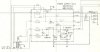
Attached is the schematic for the power board of the tuner. I noticed that the voltages I was getting out of the power transistor Q1 wasnt the same as the schematic so I replaced it. I also noticed that Cap C4 was leaking and it has been replaced.

After replacing the two components mentioned above, I get the 21V on pin 15. However, pin 11 reads 0V.

The emitter and the base pins of the transistor read 0V.

I need some help in figuring out which of the other components on the power board need replacing, so any of you electric circuit genuises out there...HELP!
 

Attachments

  • Schema.jpg
    Schema.jpg
    33.6 KB · Views: 16
What he said. With the power off, put your meter on ohms and measure from the Base to ground. If it reads a short, pull the caps and measure again. If it's still shorted, replace the Zener.
If you don't read a short, check the solder joints on that transistor. If you see a dark ring around the pins, resolder them.
Check the 2 resistors, R5 and R6.
 
Yup that was it. Replaced the 0.5W Zener diode with a 1W and it works perfectly. This project has given me the run around, more than an SA-9800 project I worked on a while ago with markthefixer's help, and all because of a Zener diode.

Thanks all for your help.
 
Back
Top Bottom