abnormalcat
New Member
Howdy howdy folks
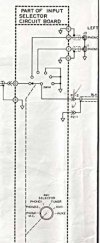
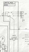
The Heathkit AP-1800 is a veritable fidget board of knobs and switches. Some of which tie into these neat linear selectors. There was some distortion and channel dropout when I first got the thing about 6 or 8 months ago off a guy on ebay which a liberal application of deoxit cleared right up. Or, it did until it got humid again. The input selector rail is in this really awkward place in the back. it's hardwired to the input RCA's and connected with really short wires to another board, making it virtually impossible to get deoxit into it. Since I needed to give it a good cleaning anyway, I figured I'd share to maybe help out people doing similar stuff in the future. Apologies for the low-quality photos, I did this late one night.
The first step is taking the bloody thing out. There are So. Many. Things to desolder. It took liberal quantities of flux, plus some new solder, to coax all the old solder out of the joints. Took me nearly an hour. Here's the pic of the board with selector taken out.
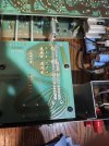
The selector itself has a few major parts: A PCB with a bunch of wires and rails. The metal housing, with a neat little system for tactile feedback to the knob, and a sliding carriage with two copper clips. The PCB is held onto the metal housing with small metal tabs bent over onto it. Carefully unbend them and it pops right out.
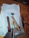

Here's the best shot of the PCB I have. It's pretty simple in construction. The wires get soldered to the input daughter board, the rails get connected to the pins via the copper clips in the carriage. Why there are 4 sets of rails I'm not sure, since the number of pins on each rail matches the total number of input options. If anyone know why these are the way they are please share!
I scrubbed everything gently with deoxit, a toothbrush, and the green scouring pad from a dishwashing sponge. Very gently, just enough to get everything nice and shiny again. There wasn't any corrosion scale or anything, but the rail furthest back towards the input jacks was a few shades darker than the others.
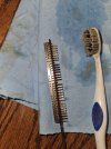
Below you can see the housing and the carriage. The bright bits in it are these small copper clips, 8 total. They come out pretty easy so if you do this don't lose them.
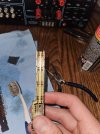
Here's a better shot of the clips and the carriage.
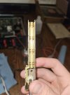
And here it is back in. If you do this, be very careful putting the PCB back into the carriage. It would be very easy to crumple one of the copper clips and a pain to find a new one. Be careful folding the metal tabs back over it too, my pliers slipped and I totally could have damaged some pins if I wasn't lucky.
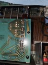
This solved all of my distortion and dropout issues, thankfully. If the issue crops up again I'll be doing similar things to all the switches, selectors, etc. just to make sure. And maybe I'll recap it at some point.
Hope someone finds this helpful, that's all for now.
The Heathkit AP-1800 is a veritable fidget board of knobs and switches. Some of which tie into these neat linear selectors. There was some distortion and channel dropout when I first got the thing about 6 or 8 months ago off a guy on ebay which a liberal application of deoxit cleared right up. Or, it did until it got humid again. The input selector rail is in this really awkward place in the back. it's hardwired to the input RCA's and connected with really short wires to another board, making it virtually impossible to get deoxit into it. Since I needed to give it a good cleaning anyway, I figured I'd share to maybe help out people doing similar stuff in the future. Apologies for the low-quality photos, I did this late one night.
The first step is taking the bloody thing out. There are So. Many. Things to desolder. It took liberal quantities of flux, plus some new solder, to coax all the old solder out of the joints. Took me nearly an hour. Here's the pic of the board with selector taken out.
The selector itself has a few major parts: A PCB with a bunch of wires and rails. The metal housing, with a neat little system for tactile feedback to the knob, and a sliding carriage with two copper clips. The PCB is held onto the metal housing with small metal tabs bent over onto it. Carefully unbend them and it pops right out.
Here's the best shot of the PCB I have. It's pretty simple in construction. The wires get soldered to the input daughter board, the rails get connected to the pins via the copper clips in the carriage. Why there are 4 sets of rails I'm not sure, since the number of pins on each rail matches the total number of input options. If anyone know why these are the way they are please share!
I scrubbed everything gently with deoxit, a toothbrush, and the green scouring pad from a dishwashing sponge. Very gently, just enough to get everything nice and shiny again. There wasn't any corrosion scale or anything, but the rail furthest back towards the input jacks was a few shades darker than the others.
Below you can see the housing and the carriage. The bright bits in it are these small copper clips, 8 total. They come out pretty easy so if you do this don't lose them.
Here's a better shot of the clips and the carriage.
And here it is back in. If you do this, be very careful putting the PCB back into the carriage. It would be very easy to crumple one of the copper clips and a pain to find a new one. Be careful folding the metal tabs back over it too, my pliers slipped and I totally could have damaged some pins if I wasn't lucky.
This solved all of my distortion and dropout issues, thankfully. If the issue crops up again I'll be doing similar things to all the switches, selectors, etc. just to make sure. And maybe I'll recap it at some point.
Hope someone finds this helpful, that's all for now.