• The move to the new server is done. There are some software and database maintenance updates in process. This has us passing the hat around to help out. We appreciate any donations. Seriously, even a dollar helps. The payment page may be found here - https://www.audiokarma.org/support.html

FM gangs... how to count?

brillcat

Active Member
Hi all, forgive me for asking a question that has likely been discussed in the past. I am wondering how to tell how many gangs a vintage FM tuner actually has? And how to tell the difference between AM and FM gangs? Is it a visual inspection, or do I have to know how to read a schematic? Also, from what I have read, gangs were replaced or made obsolete by improved solid state electronics -- is that correct? If so, did that occur in the early 1980s? Any tips/links are appreciated! Pt
 
Register to hide this ad
Most modern tuners do not use variable capacitors) for tuning; yes, that is true.
Most -- but not all -- tuners with digital displays don't have variable capacitors.

Old time, fully analog radio tuners have multiple tuned circuits in them. The "gangs" in an air-variable capacitor generally correspond to tuned elements in those various tuned circuits. Some tuners have used tuned inductors instead of tuned capacitors (see, e.g., the post below) -- but you're asking about variable capacitors.

When the "gangs' of capacitor plates are visible, you can just count 'em!

The FM "gangs" typically will have small numbers of relatively widely spaced vanes; the AM "gangs" typically have larger numbers of more closely spaced vanes.

Gang.jpg


Here's a pretty easy to see example :)
source: http://www.audioasylum.com/forums/tuner/messages/9047.html
(note that the guy who posted it got the number of AM tuned sections/"gangs" wrong!)

Here you can see the variable capacitor tuning section of what appears to be a pretty good tuner or receiver. This tuner can easily be observed to have four FM "gangs" and three AM "gangs".

From left to right: FM - AM / FM - AM / FM -AM / FM
 
Last edited:
It's probably worth noting that, in many cases, the tuner capacitor assembly is shielded and not visible.

It is also probably worth noting that there are "digital tuners" which are, more correctly, "analog tuners with digital displays".
A good example would be the pretty good modern tuners made by the Canadian company Magnum-Dynalab, although their tuners use electronically tuned inductors (called Varactors) rather than mechanically tuned variable capacitors for station selection/tuning.

http://www.fmtunerinfo.com/reviewsM-N.html

I think it is safe to say that, since sometime in the 1980s, most tuners and receivers use digital frequency synthesis tuning rather than analog tuning -- but that's about all I can tell you.
It is far easier and cheaper today to make a "digital" tuner (with a digital display, too) than an "analog" tuner (with an analog/mechanical or a digital/"frequency counter" display).

EDIT: www.fmtunerinfo.com isn't exactly my favorite hifi site, but it is a good one-stop-shopping site on... well... info on fmtuners. :)

HTH, as they say.

PS You might notice I didn't use the word "improved" to describe the digital tuning strategy with respect to its analog counterpart ;)

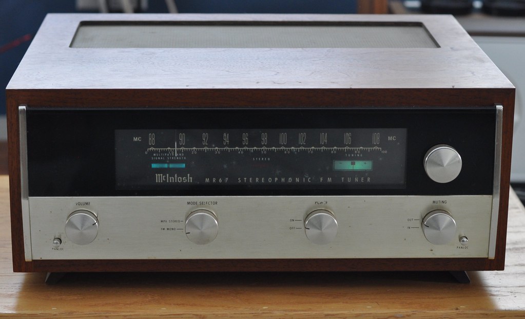
DSC_0247 by Mark Hardy, on Flickr
 
Last edited:
Thanks Mark, you've cleared up a mystery for me. (For some reason I always thought the more densely packed vanes on a variable capacitor were the FM gangs, but now I know that is for AM!) And I understand, from reading AK and fmtunerinfo, that a 3-gang FM tuner can be made to perform as well as a mediocre 4-gang FM tuner, so there's more for me to learn, but this is great info. Much appreciated :)
 
I don't know how people count these things, but remember that one of those gangs is just tuning the local oscillator, not contributing to the selectivity of the tuner, or suppressing nearby stations. So if you see four, only three are contributing to better performance.
 
Magnum-Dynalab, although their tuners use electronically tuned inductors (called Varactors)
Varactors are diodes that change capacitance with a change in voltage across them. They do not mimic inductors. If you look at a schematic of a varactor tuner, the varactor diodes are in parallel with a coil forming a tuned circuit. The voltage to change the capacitance comes from either a precision potentiometer/voltage source or from a D/A converter that takes digital information from a CPU chip and memory and converts it to an analog voltage.
 
Varactors are diodes that change capacitance with a change in voltage across them. They do not mimic inductors. If you look at a schematic of a varactor tuner, the varactor diodes are in parallel with a coil forming a tuned circuit. The voltage to change the capacitance comes from either a precision potentiometer/voltage source or from a D/A converter that takes digital information from a CPU chip and memory and converts it to an analog voltage.
You're right, I've been corrected before but - clearly - it didn't stick! Sorry about that, and thanks for correcting the thread.

The REL Precedent, though, did use variable inductors -- there may have been others.
The Precedent is a mofo of an FM tuner.
 
Permeability tuning of radios goes back to the early days of radio.

AM car radios were permeability tuned.
Capture66.JPG

Collins became famous for their radios that used using a PTO (permeability tuned oscillator).

Capture800.JPG


And BTW varactor diodes work as reverse biased diodes and a common diode will exhibit a change in capacitance with a change in the reverse bias voltage. The range and quality of the change may not be great.

Here you can see the variable inductors of the REL tuner. This is the RF front end of the tuner and you can see the variable inductors. This is the Model 646C1 which has a tuned antenna input stage as compared to the basic C version that did not have a tuned antenna input.

Capture1000.JPG

These were a mono tuner that had an output for a demultiplexer although IIRC they (REL) did not make one for this unit.
 
Back
Top Bottom