• The move to the new server is done. There are some software and database maintenance updates in process. This has us passing the hat around to help out. We appreciate any donations. Seriously, even a dollar helps. The payment page may be found here - https://www.audiokarma.org/support.html

FUJIYA DDM motor TT's

AlphaDelta

New Member
Thread about that FUJIYA DDM motor found in many known Brands

As found in many TT's there probably are lots of Issues.
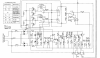
Since i'm in the middle repairing a Marlux MX-960 (same as SCOTT PS-67a (without the Auto part) and run into big problems between Whats in the Circuit diagram and actually on the Circuit board, I thought "good time to start a Thread about this DDM, and find valued Help.

My MX-960 circuit can be found here https://www.vintageshifi.com/repert...e.php?pdf=Luxman-PD-277-TT-Service-Manual.pdf

I got mine in not turning at all. I started reading this Topic https://audiokarma.org/forums/index.php?threads/hh-scott-ps-67a-infos.829182/#post-14327012

After replacing the caps and Cleaning pots, there was still no go... Replaced the The Coil powering Transistors. X7, X7, X8 and X9.

It started turning again but whit 4 shocks per full axel turn.
Replaced the IC's (simple 4458's) Zeners, and X1 to X5. So basicly all transistors are replaced.
I de-soldered them Checked on transistor itself the type and replaced with the same type..one by one... so no errors could occur...
At least that is theory.

Yet what ever I did not play ball and the 4 shock per turn remained.

So opend the motor and did some measurements on the HALL effect switches... yes one was defect..no switching done anymore..
OKay... these are from the 70ties so no chance in H** to find the originals.

I ended up ordering the ATS276 ... Marked the board where old very small one where seated to come in the same magnetic field setting.... somewhat...

Yes... it looks better less shocky... but still there.. Also RPM on 45 is to low, can't get there.....33 rpm I can get there.
I noticed That X1 has a Nice output on the C3 0.01 uf cap...On the other side of that cap it is gone... replaced it .. Nothing changed..
Released Cap C4 ...And the TT turns HIgh Speed!! way to mutch RPM

But now.... staring at the circuit diagram and the pulled transistors I noticed that there is a difference between what was on the board and what is in the circuit diagram!
X5 clearly should be a PNP transistor according to the Circuit Diagram... the original mounted transistor was a NPN Tranistor
Also C2 according to the diagram is a 22uf 6,3 Volt... Mounted is a 0,01 uf....

Maybe somebody is willing to open up a working example of this FUJIYA DDM TT and help me work out the kinks between the circuit diagram and the mounted components and help with his/her knowledge
 
Last edited:
Register to hide this ad
Okidoki girls and guy's.

I am done with this TT motor issues... I'm done trying to pinpoint the problem as bescribed in the above...I have more then 100 hours in trying to sort out this TT...by really heavy duty trouble shooting with day starting at 07.00 till 22.00 hours... it is crazy.. I have met my electronic nemesis after 30 years and more repairing everything...

The Audion/Marlux/Scott MX960 is a wel build console but I'm now only in one mindset.... get it running stable!!!

To do so I tracked down a other FUJIYA motor but with a bit different Mounting base. Were the original motor was on 4 studs, the "new" motor has it's own bracket..
As far as I can see and make up I has the same axel and cogewheel so it comes down to accurate placement.

If this new motor does not do the trick I wil set my self up for replacing every single component in one go...
Basicly build from scratch... maybe even make a new PCB with modern standards... IT WILL RUN

When it is running as it should, I will concider making it a classic beauty with new birds-eyed maple wood fineer plint, debadge, High gloss allu and chrome polished, Loose as many plastic as I dare and create a metal under plate etc...then make a new badge and rename it:

FUJIYA Nemesis MX-960
Semi Automatic Direct Drive
Linear Torque System
(AKA The Ass Kicker)

Still not sure on the ass kicker part.. :-)


Maybe....just maybe... I will source a nice SME tone arm for it..... But that is just a dream... First lets swapp that motor!
 
You stated that the motor turned with "4 shocks per full axel turn."
It's not uncommon for a DD motor to rotate in that fashion if the platter is not attached. It's trying to accelerate to speed but it has no mass to accelerate. Try it with the platter on.

BillWojo
 
Hi BillWojo
I did, because I know that "trick".
It still shocks 4 times but it is smoother due to the platter mass..
 
Very happy now!
This afternoon I got the replacement motor in. I did the swap... and Hee HO HOO... It turns stable now!!!

The original FUJIYA DDM-511F-1 is now deleted but used as source for the correct spindel.
A Marantz TT-2000 witch is a FUJIYA DDM-511F-6 Motor.

Comparing the F-1 to the F-6 shows clearly the base is different. Opening the motor shows also that the PCB has changed as have the HALL sensors.
The PCB is more logical in terms of Component connections. Basic functions are the same but the brown and yellow wires should be swaped (on the main Driver board)

So the Marantz F-6 Spindel and the MX-960 F-1 Spindel are also swaped to fit the Half automatic mechanism. Looks like the Marants spindels is a bit Shorter.

Next step wil be adapting the base of the F-6 motor to fit the Plint and half automatic mechanics. After that... make it BEAUTIFULL

Totally Happy on Christmas eve :rflmao:
 
So now the TT runs again and I enjoyd the xmas listing to it, it is time for a tear down!!
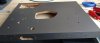
dressed chicken.jpg
As you can see the outside is screaming to be updated, and beautyfied..So of goes the the hardware, all plastic parts and yes also the sticky plastic, what's left over is this...

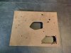
bare chicken.jpg
This bare chicken will upgraded with Waved birdeyed maple fineer.
The remaining plastic parts wil be updated towards the new/needed functions name by ingraving the text in the plastic. The plastic them selfs will be chromed (Yes, they can do that!).

I can do the fineering myself.|
The engraving and Chroming will be done by proffesionals.

Today I contacted the fineer shop, the engraver and the Chromer.... they all hav a x-mas/new-year vacation untill the 4th of january...
So plenty of time to sort out a fineer glue press..
 
Last edited:
Still working on this little TT... Worked out some supply issues, and beefed up the supply. Changed the RPM switching and control.. It is now Power on/33 rpm/ 45 rpm on one switch, and one single rpm correction adjustment instead of two seperate..

The old hole for the controls is filled in with a nice piece of timber...

This week ill recieve new RPM Switch and RPM POT... Then I can work out the new controls layout. build up and test...
If all is to my satisfaction .. it is tear down time to do some real wood veneering....

I think I go for a Waved Maple in a Bookmatched pattern

I'l keep you all posted
 
Welll long time ...no updates, but worked on my TT.

As written, I got the TT stable and it runs perfect I must say...
But there are some speed (rpm) issues that got me thinking..and I really hate that plastic bulb shining It's orange neon light..... it is not nice in my eyes...

As very common a TT uses a AC fed Neon Bulb to be to see if the TT run at the right speed and You being able to correct it..
But knowing AC 220/230 and 110/120 volts It almost never is 50 or 60 HZ exact, Hence our TT do not run at the perfect speed.

I came up with a plan to battle that issue...I took my Trio Tone generator, set it to 50 HZ Cranked the output up and connected a small Light bulb.... It did not burn... But an LED did... (hold your horses... I come to the half sine wave part)
And law and behold....It gave me a bit slower reading of the turntable then the Neon bulb gave me...After that, I doubled the frequency to 100 HZ knowing a LED is in fact a Diode and it only emits light At half the sin wave... (now let the horse free again ) :-). And sure as H***. the led gave more light, and the reading was way better..

So that would be the way to go... I found a small 1 transistor tone generator 50 HZ Circuit diagram, bought the parts, and bought a 3 Watt Amplifier kit...
The idea is to either use a light bulb driven by a Small power amp or to use two LED's bidirectional driven by that same small power-amp...

IMG_20210126_204739805.jpg
Last night I took me 1 hour to solder the idea on to a PCB... and also solder the small amp...I hope to test and frequency correct the both today and do some test runs this weekend...

I know that type of set-up should work since It is very common for Model railway enthusiasts to do the lighting of the loc's and wagons while standing still and run...

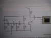
O here the circuit diagram for the sin wave generator.
IMG_20210126_204753004.jpg

Don't let that Output impression fool you... It is a pure sin-wave

The question will be... how stabil will this generator run, Involving factors could be... Supply quality, and ambient temperature, and "natural drift" of the design.. We'll see..and test
 
Welllll... Sadly that was not a great succes although i'm not completly done..
Turns out that YELLOW led do have a orange glow....I want that glow to be gone... (I know I'm a fool)

Second... the regular light is not fast enough so it just "shines" and does not give an indication...

For the LEDs I do not need an 3 watt power amp to drive them... so 10 euro's "well spend" :-(

Okay so.. lets crack on... The Yellow light witch shine orange are working perfect but there is no enough Light to have a good indication..
I do like the beam It has... So Next up..get a series of different LEDs with High output... in a variety of colors to find out the effectiv color (all but orange and blue)
Device a new generator (Cristal?) powerfull enough for driving 1 or 2 leds at 50 (100) hz

So.... here we go again.. i have trown myself an other curvball
 
A little update on this TT rebuild and remodel...
Things are going in the right direction. Figured out how to lose the enormous Speed control light.. It is reduced to a small warm white LED in a nice fitting...
And .. the LED light spreading problem is also solved...
In its time I'll show it off in a some end result pictures... I think the solution is so good and practical that it will become my Speed control light "signature" for all my rebuilds in the future (if they have originally one...)

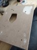
Finished Filling and sanding what need to be filled and sanded
IMG_20210209_104721811.jpg

Hoping I can get hold of Waved Maple in book matched sheets in the not to far future...(few weeks)
In terms of color... I don't want to go to dark...but I want to show of the waved maple..Might even satin with a tiny bit of stain....Or stain a little and use a citrus oil the also use on open maple guitars necks..


The untreated holes you see are unseen under the platter (chassis mounting points) or have a function in the design..

Let's toddle on....
 
Hi Guys,

I'm working on the same board on a luxman PD 277.
When I got it, it was dead, but after replacing some transistors and caps it runs again, and pretty stable, or so it seems.
2 issues:
1 - when the turntable is in one specific position it wont start from itself, it needs a little push and then starts turning, in other positions it starts but you can see it hesitates a bit. So a but more torque would be welcome.
2 - when I measure wow and flutter, I can't get it to go under the 1,1% which is too much. The service manual states what pots to use to adjust (3 pieces) but does not describe the procedure, it literally states not to touch it...

So after putting a lot of effort in the turntable i'm out of ideas, does anyone has the golden tip for me?

Thanks
 
Hi Roel,
Vintage-Audio.nl (Auke) from Holland here ...

I got my TT running stable and fast starting after replacing the adjustment pots on the PCB.(after replacing the motor).
After that it was realy self explaning how to adjust for the best momentum on running and starting.

But it would be helpfull If you could point out what You have done to get it running again..What did you replace, what is still original etc.
For one person replacing the mains plug is a lot of effort and for the next guy replacing all caps is... etc....so "allot of effort" can mean a lot of things..

But just to get things started.....It well could be that the oil it the spindle is not very oily anymore and therefor not letting the TT start properly.

Okay there you have a few possible causes... It really is a good set-up (pcb and Motor) but it is getting fairly old.

Greeting from Enschede Holland
 
Hi,
So, as I said I've got the turntable and it would not start.
Apart from repairing a broken armstand and anti-skating stick I did the following to get it running again
  • I've replaced X1, X2, X3, X4, and the caps around it on the board, I can't remember exactly which ones.
  • The motor has been disassembled, cleaned and lubed
  • The pots have been cleaned with kontakt 60 / WL / 61 but not replaced
I used an iphone app called turntable RPM to measure the RPM and wow and flutter, on similar turntables this value shows 0,12% which is more than it should but that is due to the fact that there is a fairly heavy iphone on the platter on one side which makes the platter unbalanced. However, I cannot get it beneath 1,1% when adjusting VR 3, 4 and 5. And this is a process of trial and error since I don't have the procedure. For example, which one does what and which one should I adjust first and to what value?

Dankjewel!
 
Hi Roel

Okay You have replaced the 4 transistors that are responsible for the Signal detection / comparison / generation
upload_2022-1-28_10-48-50.png

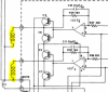
Those are important but since It wil not start but keep running (but not in spec) when helpt I suspect that X6,up to X9 witch are motor coil (motor coils in yellow) drivers could be out of spec..but there other possible causes to research and rule out first.

upload_2022-1-28_11-15-36.png

Your TT is not far from running right IMHO.
Since you can get it running almost smooth, but out of spec it somehow tells me your motor is okay. Same goes for IC1 But it is cheap so It can't hurt to go save and replace IC 1 anyway.
If it where mine I would replace all VR pots without any question.. The Originals are open models, had there share of aging due to moist, possible nicotine and whatnot in the last 30 years or so. In many cases they do not clean up very well. They are cheap and readily available and easy to replace.

When replaced, set them Centre. This could help you to get in to spec again. Now you should be able to adjust to make it run smoothly. If not replace X6 up to X9 (I might have them in stock but have to check) They are not expensive to buy but European electronic parts stores might not have them in stock.

The same goes for the Supply Caps... if 1 is off... the chance is it has a nasty "hum" in the supply and the rest of your TT electronics then could be off... Just replace C12 and C13


VR1 and VR2 are RPM pre sets... I usually try to set the External RPM in mid position and then set the VR1 and 2 to the correct speed. That way you have maximum correction option +and - on the actual RPM while spinning a disk.
VR3 and 4 are there to adjust timers to get the coils in sync.

If your TT works well You then adjust them to run as smooth as possible and as silent as possible... There is a sweet spot. You even can hear it!

Let us know what your findings are...
 
Very old thread, I know... but:

I have a problem with a Luxman PD 277, same motor, same board.

As soon as X6 - X9 are installed it blows both the secondary fuses (500 mA T in Europe) even when the motor is completely disconnected. But the motor may have shot the transistors before.

So first I'd like to check the motor itself, does anyone (hopefully) know the resistance values of the motor coils ?

Thanks a lot in advance,

Martin
 
Back
Top Bottom