• The move to the new server is done. There are some software and database maintenance updates in process. This has us passing the hat around to help out. We appreciate any donations. Seriously, even a dollar helps. The payment page may be found here - https://www.audiokarma.org/support.html

Fulton J Modulars - bringing the best back to life

JoshHendi

^ElectroNerd^
Subscriber
Starting this thread to document my attempt on restoring these amazing speakers. I was the very lucky purchaser of these years ago. I thoroughly enjoyed them over the years and love seeing the reaction to all of my friends (both audio enthusiasts and not) when they see the size of them, and when they hear them...

For those who may not know the magnitude of these speakers, I have included some pictures and links below. Sporting an 6 panel electrostatic tweeter array, a 'mid-range' bookshelf speaker with two tweeters and an 8" woofer, and the bottom housing that holds a 10" and 12" woofer, along with the massive modular crossover design. While I could go into more details on these, I will leave two reference links below:

Fulton Speaker Models parts reference
FMI Discussion Thread
My Fulton image gallery

I told myself when I got them, I would enjoy them as-is until a problem arises, at which time, I will start the restoration process. After they took a break for a few months, I went to listen to them and one of the tweeter array's quit producing sound. One of the tweeter fuses in the power supply are popping. This is where the rebuild process begins.
 

Attachments

Last edited:
Register to hide this ad
Step One: Fix the fuse popping issue

There are two fuses in the ESR crossover. The one that is going on me is the 1/8A fuse right at the AC plug. I have removed the crossovers to begin troubleshooting.

- Did visual and resistance checks for any breaks or blown parts
- Replaced the original 3KV diode with three 1N4007 diodes in series

To-Do:
- Find and fix the issue that is causing the 1/8A fuse to pop
- Replace capacitors
- Replace resistors
- Touch up all suspect solder joints
- Replace power cords with longer, polarized cables
 

Attachments

  • FultonESR.PNG
    FultonESR.PNG
    493.7 KB · Views: 35
Last edited:
Upon getting into the crossover/power supply and doing some probing/testing, I fear the 1:8 power transformer (T2 on schematic) is bad... I used a DMM to compare resistance readings of the transformer from the good unit vs the one in question, and am getting OL reading when checking the primary's/secondary's. Will soon have signal generator to verify, but I fear the transformer is bad. In the mean time, I will replace the resistors and caps and diode as planned...

Don't know a whole lot about transformers as far as what to look for in replacements.

Can anyone point me to, or give me advise, on looking for replacement transformers? And would ideally replace both to keep things matched (unless I land a miracle and get an original)
 
Last edited:
I am wanting to install a longer, polarized power plug for these, can someone with more knowledge look at the schematic and tell me which way I should install it?
 
Hi Josh,
Neat project. Your new power cord should have the hot leg connected to the fuse. A 1:8 stepup power transformer would be 960V RMS with 120 on the primary. Be careful with R6 which is across the secondary. A 1/2W resistor won't take 1000V RMS (over 1350V peak) at any value in the range listed. 270k with 1000V across it is 3.7W dissipation.
John
 
Starting this thread to document my attempt on restoring these amazing speakers. I was the very lucky purchaser of these years ago. I thoroughly enjoyed them over the years and love seeing the reaction to all of my friends (both audio enthusiasts and not) when they see the size of them, and when they hear them...

For those who may not know the magnitude of these speakers, I have included some pictures and links below. Sporting an 6 panel electrostatic tweeter array, a 'mid-range' bookshelf speaker with two tweeters and an 8" woofer, and the bottom housing that holds a 10" and 12" woofer, along with the massive modular crossover design. While I could go into more details on these, I will leave two reference links below:

Fulton Speaker Models parts reference
FMI Discussion Thread

I told myself when I got them, I would enjoy them as-is until a problem arises, at which time, I will start the restoration process. After they took a break for a few months, I went to listen to them and one of the tweeter array's quit producing sound. One of the tweeter fuses in the power supply are popping. This is where the rebuild process begins.

Wow, those are some very nice looking speakers. I can only imagine the sound quality.
Michael
 
I'm listening to my pair of Fulton FMI80s right now, and will follow this thread with enjoyment.

You have to post a good picture of the crossover assembly here! The only picture that I could find is pretty grainy. It's awesome in it's klugy-complexity!
 
Hi Josh,
Neat project. Your new power cord should have the hot leg connected to the fuse. A 1:8 stepup power transformer would be 960V RMS with 120 on the primary. Be careful with R6 which is across the secondary. A 1/2W resistor won't take 1000V RMS (over 1350V peak) at any value in the range listed. 270k with 1000V across it is 3.7W dissipation.
John
Hey John, thanks for the reply and info! R6 is five 270k 1/2w resistors connected in series. Also, the 1:8 transformers seems like a 8:1 transformer but used in reverse... The 120v connects to the 'smaller secondary' wires and the 960v comes out of what would normally be the primary, in this Fulton-like configuration. On the bad tweeter, that power transformer is open and I will have a original replacement in around the 20th-25th, which is when I will have an update on this project. While I wait, I will get new polarized plugs installed. Thanks!
 
You have to post a good picture of the crossover assembly here! The only picture that I could find is pretty grainy. It's awesome in it's klugy-complexity!

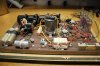
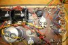
Here are some pics of the main crossovers, located in the bass cabs. And Js with covers vs without
 

Attachments

  • 20161001_174833.jpg
    20161001_174833.jpg
    50 KB · Views: 78
  • 20161001_174848.jpg
    20161001_174848.jpg
    99.1 KB · Views: 80
  • 20180415_182122.jpg
    20180415_182122.jpg
    37.5 KB · Views: 79
Awesome! Thanks!
I love the starter solenoids as inductors. If you aren't careful, you could spend a ton for capacitors on those eh?
They look to be in great shape. Congratulations!
 
Yes a main crossover recap will happen one day, but not until its absolutely needed. Yea I'd imagine about $150 worth of caps for the replacement project, when that time comes. For now, just trying to get the tweeters done to get them operating again
 
Very nice! It always does my heart and mind good to see these older speakers brought to life and kept as close to original as possible, instead of all the bodgers and choppers out there! Good on you, enjoy them, hopefully for a long time!
 
Update: One of the ESR-6s had a bad power transformer (the 'secondary' was OL). I recently sourced a replacement which should be here in a couple of days. In the meantime, both ESR-6 powersupply/crossovers have gotten new components... New caps, resistors, and powersupply diodes. Also replacing the original power cord with a much longer, polarized one. Considering the ESR-6s sat atop of the massive J bass, the original powercord was much too short. And lastly, removed the fuse breaker and mounted a standard fuse mount

Also replaced the single cap in the FMi-80s and got new sealant for a air tight seal

Once the power transformer swap is complete, the ESR-6s and FMI-80s will be complete, and the real fun begins on the main crossoveer
 
Last edited:
My brother bought a pair of FMI80 s and a set of the electrostatic panels with
the idea of building the complete system. The PSU and crossover sure do
look complex.
Is there a crossover schematic available?
 
Is there a crossover schematic available?

There is a schematic available for the ESR-6 (and the FMI-6) estat panels, but for the main crossover in the woofer cabinet, the answer is no.

Fulton was a notorious tinkerer, and he never got a (in his mind) 'finished' design... I have two sets of J woofer cabs, and the crossovers are a bit different, and any pics Ive seen online are also not quite the same.

Attached some stuff
 

Attachments

Last edited:
Main Crossover Board Capacitors
Attached is an image of the main crossover board Ill be working with all the capacitors labeled. I made this thread looking for input in regards to what type of cap I should use to replace the originals.

C1-2: 8,000uf, 18v
C3: 75uf, 200v
C4-6: 2uf, 130v
C7-10:
C11: 10uf, 370v
 

Attachments

  • J Caps.jpg
    J Caps.jpg
    126.9 KB · Views: 21
  • IMG_4792.JPG
    IMG_4792.JPG
    117.7 KB · Views: 15
  • IMG_4793.JPG
    IMG_4793.JPG
    111.3 KB · Views: 13
  • IMG_4794.JPG
    IMG_4794.JPG
    131.1 KB · Views: 13
  • IMG_4795.JPG
    IMG_4795.JPG
    137.5 KB · Views: 11
  • IMG_4796.JPG
    IMG_4796.JPG
    92.2 KB · Views: 13
  • IMG_4797.JPG
    IMG_4797.JPG
    95.6 KB · Views: 12
  • IMG_4798.JPG
    IMG_4798.JPG
    76.4 KB · Views: 13
Back
Top Bottom