Thanks, regarding bypassing audio path electrolytics. The reactance of the 1000pf at 10k-20kHz is much greater than that of a 1uf or 47uf coupling cap so I'm not seeing that as the preferred path for the HF's. OK, it's just a basic understanding, probably a difference between ideal cap behaviour and real world. Clearly the Sansui techs included the cap for a reason.


You are using an out of date browser. It may not display this or other websites correctly.
You should upgrade or use an alternative browser.
You should upgrade or use an alternative browser.
Function of Bypass film caps
- Thread starter Soundphile
- Start date

Of course, I understand.Thanks, I'm not on a crusade or anything, just trying to understand...


JoseHH
Super Member
In this case it would be better to put them right at the printed circuit as close to the circuit that demands the current in a transient because in this case it will compensate for any inductance of the rail wires. Normally rails are twisted together tightly to minimize the loop area determined by the path of the current flow out from and into the power supply. But there is always some small resistance and some inductance in the wires, so placing a capacitor at the delivery point would help. Sometimes it is not possible to do that. The AU-919 and the AU-D707X and the AU-517 have film capacitors in parallel with the power supply capacitors, but I speculate that they put them because the capacitors of that era did not have sufficiently low equivalent series resistance and inductance. Chemistry is also slow, so they probably put smaller "faster" capacitors to deliver current peaks when needed.And also discussion about the best location for the PSU film bypass capacitors. Was it just 'convenient' to mount them on the lugs of the large electrolytics? or was this placing the solution closest to the perceived problem? Would it be better to place the bypass capacitors closer to the audio circuitry? on the driver board for example? - the jury is still out on that one...
With regards to signal path, putting a small capacitor in parallel with an electrolytic I always thought that was because at high frequency (I would say close to 20KHz) the electrolysis chemistry becomes limiting because there is transport of ions to and from the electrodes across the electrolyte of the capacitor. So a "slow electrolytic capacitor" may appear as it is not there if the internal chemistry does not do the job. At sufficiently high frequency any inductance will show up, so the capacitor becomes an attenuator at high frequencies. A film capacitor can respond much faster because it only needs to polarize the dielectric film and there is no ion motion.
To see if this speculation is correct, one needs to measure the attenuation of a sinewave across an electrolytic capacitor and vary the frequency. I would expect a maximum at some frequency and then a decline due to the chemistry and/or the parasitic iductance of the capacitor. Then put a film capacitor in parallel and see if more signal passes. Is tedious but doable.

GrisPato
Super Member
Good explanation.
Just always wondering about this. It's really difficult to find good information about what is considered high frequency in electronics. As far as I can find audio amplification is considered LF spectrum. I can find information how ceramic and filmcapacitors are considered superior in high frequency applications but they are talking than about at least MHz to GHz. So my question is: can we consider the lowly 20-40KHz as a high frequency for a capacitor, even an electrolytic?
at high frequency (I would say close to 20KHz)
Just always wondering about this. It's really difficult to find good information about what is considered high frequency in electronics. As far as I can find audio amplification is considered LF spectrum. I can find information how ceramic and filmcapacitors are considered superior in high frequency applications but they are talking than about at least MHz to GHz. So my question is: can we consider the lowly 20-40KHz as a high frequency for a capacitor, even an electrolytic?
JoseHH
Super Member
For electrolytic capacitors, the few tens of kilohertz is considered high frequency, well within what is considered a healthy bandwidth of audio amplifiers. In any application above 1 MHz they are not good, and rarely used. You might see Tantalum capacitors in these applications if an electrolytic is used. Otherwise ceramics are preferred in RF where small capacitances fulfil the function needed.So my question is: can we consider the lowly 20-40KHz as a high frequency for a capacitor, even an electrolytic?
GrisPato
Super Member
Not to take your words in doubt but why do manufacturers than give specifications for there capacitors on for example ESR and ripple current at 100 KHz? This would be useless information than if nobody uses them at that frequency?For electrolytic capacitors, the few tens of kilohertz is considered high frequency,
I understand that powersupply decoupling caps of like 10000uF have a resonance frequency close to the audio frequency but they mostly have to work at 120 Hz. But for capacitors from like 47- 1 uF the resonance frequency is mostly on and above 1 MHz . So there esl is going to be small still compared to impedance. About ions speed I have to say I know nothing about the speed of ions and what is fast or slow. Can not imagen they can not keep up with 20000 Hz , which would mean charging and discharging every 50000 nS and there time to move from one side to the other side in electrolytic being in the range of 3- 50 nS for what I can find about ions.
Hope to learn more
JoseHH
Super Member
Hello @GrisPato . No problems. You are correct, the resonant frequency of small capacitors could be in the MHz range but still the capacitance does not remain the same across the frequency spectrum (I refer only to Aluminum electrolytic capacitors). What I meant is that the ion motion takes time to occur in the liquid electrolyte and the main reason for this is that the ions do not move between two parallel plates of aluminum but rather from a highly porous electrode into another highly porous electrode. This porosity causes that the trajectory the ions have to cover could be quite tortuous, and therefore is not just moving across plain liquid. The organic electrolytes used can be quite voluminous ions and the viscosity of the liquid is what limits the motion of the ions. In the few 10s of kHz the ion motion could be such that in one period of the signal the ion does not have enough time to get close enough to the electrode surface where it is supposed to accumulate in order to generate the polarization that in the end accumulates the charge of the capacitor. What you see is that at few KHz the capacitance starts to drop relative to that of the nominal value of that aluminium capacitor. Because increasing the temperature usually causes the viscosity to decrease, if you operate the capacitor at high temperature the capacitance drop is smaller, that is to say that the capacitor holds its capacitance up to higher frequencies. At low temperatures they are quite disastrous. But operating the capacitor at high temperatures causes other degradation phenomena and it shortens their life.
I have read some articles about how capacitors work, and I am just repeating what I have seen. If you look at figure 4, you will see where did I get this idea from. This is supposedly a 100 uF capacitor. Also, please note in the said figure that at higher temperatures, where the curves shift up towards the nominal capacitance value.
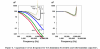
The figure also explains why Tantalum electrolytic capacitors are preferred in RF work. (why they are lousy for Audio is another story...).
EDIT:
I decided to attach a second article. On page 6 they talk about the effects I mentioned in my comments.
I have read some articles about how capacitors work, and I am just repeating what I have seen. If you look at figure 4, you will see where did I get this idea from. This is supposedly a 100 uF capacitor. Also, please note in the said figure that at higher temperatures, where the curves shift up towards the nominal capacitance value.
The figure also explains why Tantalum electrolytic capacitors are preferred in RF work. (why they are lousy for Audio is another story...).
EDIT:
I decided to attach a second article. On page 6 they talk about the effects I mentioned in my comments.
Attachments
Last edited:
GrisPato
Super Member
Interesting information. For sure could explain why some of the capacitors used in the late seventies and eighties perform well at audio frequency: bigger sizes because of less etching so less capacitance for size but also less losses and resistance when frequency goes up. I have seen the difference.
10uF-50V 5 times the volume of an 22uF-50V
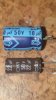
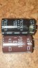
Or this
4,5 times the capacitance in a 10% smaller package
Also shows the importance of low ESR besides the warming up, less capacitance losses at higher frequency.
At the website from Ishino lab the former Sansui engineer also mentions they found that less etched anodes gave better sound.
Thanks @JoseHH for enlightening me a little more.
10uF-50V 5 times the volume of an 22uF-50V
Or this
4,5 times the capacitance in a 10% smaller package
Also shows the importance of low ESR besides the warming up, less capacitance losses at higher frequency.
At the website from Ishino lab the former Sansui engineer also mentions they found that less etched anodes gave better sound.
Thanks @JoseHH for enlightening me a little more.