• The move to the new server is done. There are some software and database maintenance updates in process. This has us passing the hat around to help out. We appreciate any donations. Seriously, even a dollar helps. The payment page may be found here - https://www.audiokarma.org/support.html

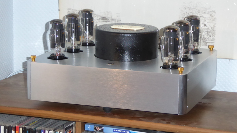
Futterman OTL 3 w/ upgrades

or if you can make the fan an exhaust, and bring air in at the front that will help cool the caps. If thats an inlet fan its just pushing hot air forward. By the design of that fan I question how much air it can actually move in or out, it looks like the motor frame mostly blocks the air vent anyway.
Hmmm -- good flag. I will take a much closer look then. Plus side is there are many fan options so shouldn't be hard to upgrade if needed.
 
Plus side is there are many fan options so shouldn't be hard to upgrade if needed.

Sure @Jfaustus ! You amp would be less suffering in the meantime... :cool:

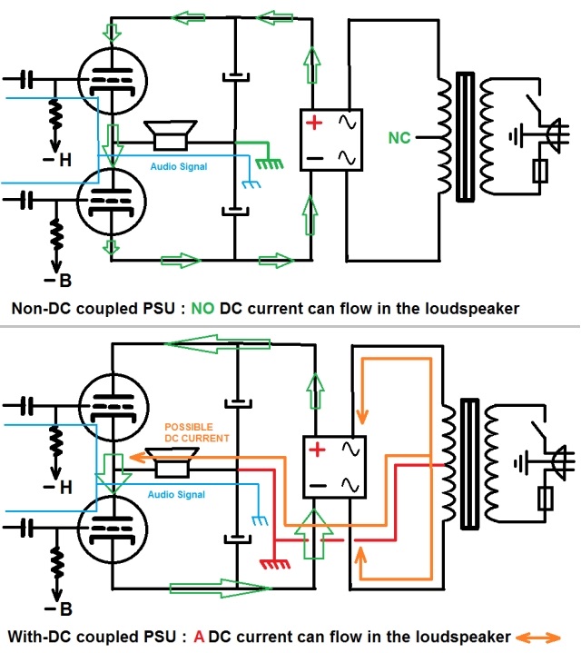
You wrote that your OTL-3 has output coupling caps, right ? So this amp doesn't have a floating power stage supply ? Unlike what I have done one mine (schematic one) :

4UyvJb-OTL-PSU-DC-and-non-DC-coupled.jpg


T
 
Those speakers look fantastic!

Thanks at my pal Alain @techguy0192 !

It's his personal previous designs and experimentations that made him come to that finished version. It's not a folded back loading horn, but a rolled one...

My Wife compared it to the famous Gaffophone, built by Gaston Lagaffe - a well known French comics strip :

1788284162519.png

1788284373061.png
:idea::crazy::D;)

Kidding apart : those Wide-Band back-loaded rolled horns sounds also fantastic, notably with low power output OTL amp like mine or my Friend's (below) :

20041212293325019416738739.jpg


T
 
Last edited:
early OTL amps were single rail power supply, the point where the plate and cathode of the two outputs come together sits at 1/2 the power supply voltage. Need an output cap for that design. C12 on this one.


1788284645125.png
 
early OTL amps were single rail power supply, the point where the plate and cathode of the two outputs come together sits at 1/2 the power supply voltage. Need an output cap for that design. C12 on this one.


View attachment 3828187
Hey that looks familiar! :rflmao: :rflmao: :rflmao: :rflmao:

Y'll are better at deciphering schematics than I am. Here is the original OTL-3 schematic. Of course it bears little resemblance to the
Kaye modded version. But @tubelectron it does appear to have 4200µf on the output -- C15, kinda right in the middle there. My assumption given that there are two different banks of big caps in mine was that Kaye preserved this and +/- doubled the speaker caps. He definitely kept the transformer as I have seen the OTL-3 stamp on it.

nyal otl3.jpg
 
same supply design, single rail, output coupling cap to block DC from the speaker.

likely multiple caps in parallel to make it larger, and/or lower ESR. Generally lower value caps have less ESR, and when they are in parallel that value becomes even smaller.
 
same supply design, single rail, output coupling cap to block DC from the speaker.

likely multiple caps in parallel to make it larger, and/or lower ESR. Generally lower value caps have less ESR, and when they are in parallel that value becomes even smaller.

And if there's none (= direct coupling to the speaker), that's even better... ;)

T
 
in theory, obviously needs a different design for the power supply and such to make that possible, but if something goes bad there is no voltage isolation. THink I'd have to put a DC protection relay like solid state amps have to feel entirely comfortable with that.

then again I own a solid state amp without a relay and its known for roasting speakers and i haven't added a relay to that.

at least this takes feedback from the speaker side of the cap so its compensated for.
 
in theory, obviously needs a different design for the power supply and such to make that possible, but if something goes bad there is no voltage isolation. THink I'd have to put a DC protection relay like solid state amps have to feel entirely comfortable with that.

then again I own a solid state amp without a relay and its known for roasting speakers and i haven't added a relay to that.

at least this takes feedback from the speaker side of the cap so its compensated for.

Yes - a great number of transistor amps have a supply like in the second schematic (lower). And nobody seems worried about that... I have seens Peavey PA and Ampeg V6B killing-smoking with DC amperes the moving coil of speakers, because one of the power transistors went bad...

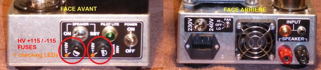
Now looking to the first schematic (upper), you understand why this floating DC power supply can't kill the speaker if a tube goes bad. That's what I use in my U-OTL. I have made the security tests : removal of a tube, shorting of a tube (the + and the - going directly to the 6080 are each protected by a fuse, just in case).

4UyvJb-OTL-PSU-DC-and-non-DC-coupled.jpg


The 6080 protection fuse located on the front face, each with a failure red Led indicator :

BeMiOb-M1-Copie.jpg


That said, my 10WRMS U-OTL have nothing to do with those Big OTL Amps, like the 200WRMS upgraded Futterman OTL-3 owned by @Jfaustus : not the same power involved, not the same complexity of the circuits, hence a reduced risks of failure.

That said, if you look at the schematic of the well-known TECHNICS 20A - a 2x75WRMS OTL - you note that the power supply is not DC floating, while there's no speaker coupling capacitor... A 3A protection fuse is placed in series with each speaker output, and a BALANCE METTER is provided to check if there's no DC imbalance going to the speakers :

technics_20A_1965_75w_on_16ohm_50h-b26.gif


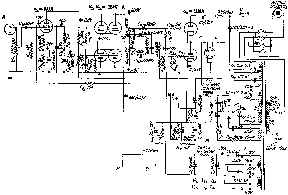
Conversely, the smaller 2x 20WRMS Takésué OTL amp, with only a single 6336 per channel, offers the DC floating supply circuit, so no speaker coupling cap is required :

6336_2.gif

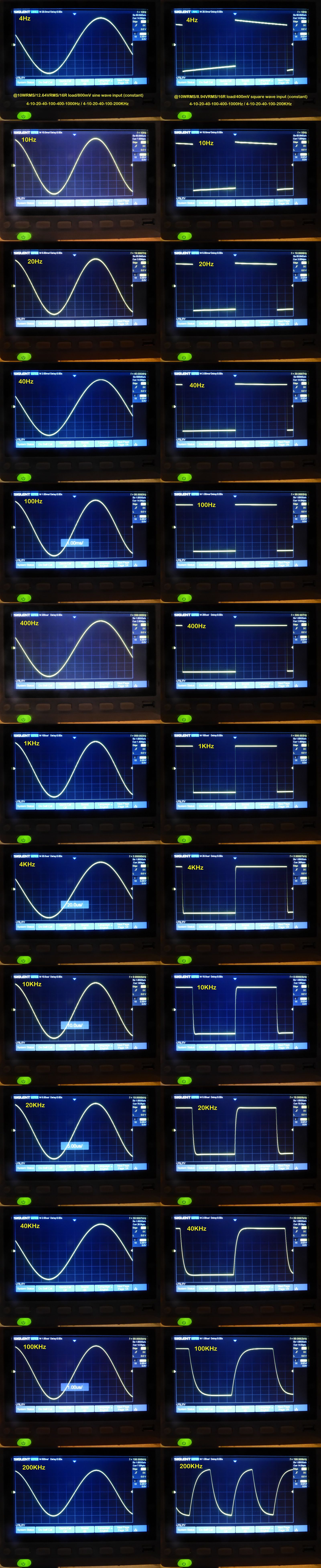
IMHO, at least for the little / moderate OTL power amps, the DC floating supply / Output Cap Less is a very suited and safe formula. See the square waves of my U-OTL taken at their nominal power output of 10WRMS @16Ohms, from 4Hz to 200kHz :

c4xUPb-U-OTL-WAVES-04-05-2023.jpg


T
 
yeah no ground reference on the output plate supply means a short won't do anything. Same idea as an isolation transformer on the mains, a short from either side to ground doesn't do anything because there is no other connection so there can't be a voltage difference.

Needs a dedicated winding on the transformer though, not a big deal. Two transformers, or a transformer with two HV secondaries so the other tubes can have a normal ground reference will get it done. Easy enough to do on a new design, bit more difficult to retrofit an existing one.
 
Needs a dedicated winding on the transformer though, not a big deal. Two transformers, or a transformer with two HV secondaries so the other tubes can have a normal ground reference will get it done. Easy enough to do on a new design, bit more difficult to retrofit an existing one.

Yes ! That's a fact... This moreover represents supplementary parts, because of the required additional power supplies. I have the project of building a single 6080 compact monoblocks OTL amps :

1788416331118.png

... But entering all the parts becomes a real challenge in such a small format - because of the multiple PSUs, or the big output cap !

T
 
Back
Top Bottom