
• The move to the new server is done. There are some software and database maintenance updates in process. This has us passing the hat around to help out. We appreciate any donations. Seriously, even a dollar helps. The payment page may be found here - https://www.audiokarma.org/support.html

G-3000 Repair & Rebuild - Dead Channel Question

dups68

New Member
I recently picked up a G3000 as working that has a dead right channel and would appreciate a bit of advice! When I got it home I hooked it up to some junk test speakers just to see what I had. Right channel was dead with a bit of a hum (both through the speakers and headphones) and the left channel sounded okay through headphones but a bit weak on the speakers (maybe it was just the speakers).

I gave it a quick deoxit hoping that would solve it and no dice. I then decided to check the voltage at the speaker terminals. Left channel looked fine but the right threw out 30Vdc! At that point I decided to tear it apart to see what was up.

Following along with the service manual, I took voltage readings back on both channels to compare the results. On both channels the voltages were ball park-ish around TR01/02 and TR03/04 (reading slightly high at 13.5V and 14.1V for each respectively).

Where things started to fall apart for the right channel was at R48/IC02. On the diode side of that resistor the voltages looked fine (dead on the 13V), but jumping over to the dual transistor/IC side, the reading was 11.3V rather than the 0.6V listed in the manual. From here on voltages were off down the line. Around R50 voltages were 11.3/11.4 rather than -30.5/-31, voltage on the emitter of TR14 was 27.8 rather than -0.6V, etc, etc

I checked the resistor resistance in circuit and it read fine and matched with its sister resistor in the other channel (which read nearly spot on to the 0.6V).
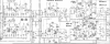
upload_2022-10-28_14-48-4.png

So I guess my question is the censuses that IC02 is the likely point of failure? Its a 2SA798 dual transistor which I saw was on the 'shoot on sight' list. Is the best replacement still pairing up two KSA992s?

What other parts downstream are could be damaged due to its possible failure? While doing the work I figured that recapping would hurt and also replace the mirror parts in the other channel for anything swapped out in the right channel.

Nothing looks burnt out on the board but I know that failure isn't always that obvious.
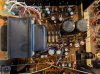
upload_2022-10-28_15-9-41.jpeg


Also , it looks like someone was in here before and I see a few mystery parts scattered around. TR11 was originally a 2SC1211 by the manual but has been replaced by an ECG188. Also the 2SC1986 output transistor were replaced by some unidentifiable (by my googling) transistors. I have no idea if the replacements are appropriate so I was planning on just replacing them (unless someone knows these would be suitable in place)
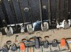
upload_2022-10-28_15-17-11.jpeg

upload_2022-10-28_15-27-47.jpeg

Any help would be greatly appreciated!
 

Attachments

  • upload_2022-10-28_14-48-4.png
    upload_2022-10-28_14-48-4.png
    337.1 KB · Views: 7
Register to hide this ad
I recently picked up a G3000 as working that has a dead right channel and would appreciate a bit of advice! When I got it home I hooked it up to some junk test speakers just to see what I had. Right channel was dead with a bit of a hum (both through the speakers and headphones) and the left channel sounded okay through headphones but a bit weak on the speakers (maybe it was just the speakers).

I gave it a quick deoxit hoping that would solve it and no dice. I then decided to check the voltage at the speaker terminals. Left channel looked fine but the right threw out 30Vdc! At that point I decided to tear it apart to see what was up.

Following along with the service manual, I took voltage readings back on both channels to compare the results. On both channels the voltages were ball park-ish around TR01/02 and TR03/04 (reading slightly high at 13.5V and 14.1V for each respectively).

Where things started to fall apart for the right channel was at R48/IC02. On the diode side of that resistor the voltages looked fine (dead on the 13V), but jumping over to the dual transistor/IC side, the reading was 11.3V rather than the 0.6V listed in the manual. From here on voltages were off down the line. Around R50 voltages were 11.3/11.4 rather than -30.5/-31, voltage on the emitter of TR14 was 27.8 rather than -0.6V, etc, etc

I checked the resistor resistance in circuit and it read fine and matched with its sister resistor in the other channel (which read nearly spot on to the 0.6V).

View attachment 2699747

So I guess my question is the censuses that IC02 is the likely point of failure? Its a 2SA798 dual transistor which I saw was on the 'shoot on sight' list. Is the best replacement still pairing up two KSA992s?

What other parts downstream are could be damaged due to its possible failure? While doing the work I figured that recapping would hurt and also replace the mirror parts in the other channel for anything swapped out in the right channel.

Nothing looks burnt out on the board but I know that failure isn't always that obvious.

View attachment 2699765


Also , it looks like someone was in here before and I see a few mystery parts scattered around. TR11 was originally a 2SC1211 by the manual but has been replaced by an ECG188. Also the 2SC1986 output transistor were replaced by some unidentifiable (by my googling) transistors. I have no idea if the replacements are appropriate so I was planning on just replacing them (unless someone knows these would be suitable in place)

View attachment 2699766

View attachment 2699774

Any help would be greatly appreciated!
Work your way from the outputs back. In direct coupled amps, it's not unusual to have voltages all over the map when an output and/or driver shorts.

Don't recap it until it's fixed.
 
Thanks for the advice! Just ordered a load of parts off mouser so we'll see if I can get this thing singing again.

Related question, two of the screws for the speaker connections on the back are pretty busted up (as can be seen in the photos). Anyone know where to track down some replacements? I've tried googling but can't seem to find what i'm looking for
 
Also, when going through I've read that the pair of KSA992s should be matched. Are they any other transistors that I should ensure are a close match as I work through?
 
Differential input pair matching (KSA992 with emitters tied together) should be enough to keep DC offset to a minimum. Check all fusible resistors, emitter resistors, semiconductors as well
 
Thanks for the advice! Just ordered a load of parts off mouser so we'll see if I can get this thing singing again.

Related question, two of the screws for the speaker connections on the back are pretty busted up (as can be seen in the photos). Anyone know where to track down some replacements? I've tried googling but can't seem to find what i'm looking for

Hi,

Re the speaker terminals, I don’t think you will find anything new that will fit. There are a pair of terminals available from that auction site, listed as from a G-4500, but the part number is the same as the ones used on the G-3000 (a check the service manuals for both receivers shows this). Please confirm via your own investigation. Not cheap but options are limited if replacement is required.

Here is the link

https://www.ebay.com/itm/2949491406...9zEeCk/TWK9ptvBvIa/M3BgDQ=|tkp:Bk9SR_CI7I6NYQ

Hope this helps

Cheers
John
 
Appreciate the tips and help! Finally got my parts in this week and had some time today to get started. Figuring the 2SA798 was the issue in the right channel, I dropped in a match set of thermally bound KSA992FB's. Gave it a test and no luck. Was still seeing DC at the speaker terminals and positive voltages around R50.

Started tracing the voltages back around the board to see if there was anything else up that might be causing the issue. Traced back to R68. -31.8V on one side and +11.3V on the other. AH-HA! This one happened to be one of the fusible resistors on the board and thankfully I ordered replacements for every fusistor in this thing (thanks p4spooky!)

Pulled it out and took a measurement on my cheapo meter. Rather than the 100ohms is should have been it was reading nearly 90Kohms. Swapped in a new metal film resistor and the channel is back!

Only issue now is that upon startup there is a pretty loud "pop" coming through the speakers. Based on some previous threads, the cause may be some worn caps (possibly C39?) so going to work on recapping (as well as replacing the 2SA798 and some shoot on site transistors).

Should the output transistors also be replaced with complimentary pairs? Or should it be okay with the original 2SA771's and the replacements that someone previously put in there for the 2SC1986's?
 
Great progress @dups68

Recently worked on my G3500 that had a blown right channel. Ended up replacing all transistors in this unit since right channel PNP output and its driver was shorted. Please see the pictures to give you an idea on the transistors I used at various points in the circuit as replacement. Added a protect board and it is working great and sounds amazing. HERE is the link

You can replace the outputs with KSD526Y and KSB596Y and see if it helps with the pop. I suspect the pop is from high DC at the output upon power up before the amp settles down.
 
Last edited:
Great progress @dups68

Recently worked on my G3500 that had a blown right channel. Ended up replacing all transistors in this unit since right channel PNP output and its driver was shorted. Please see the pictures to give you an idea on the transistors I used at various points in the circuit as replacement. Added a protect board and it is working great and sounds amazing. HERE is the link


impressive job!
 
@p4spooky thanks! I ordered a few output transistors so I'll try swapping them out as well as the caps.

Your photos look clean, that g3500 looks better than new! what does the protection board add? is that something I should consider adding to my unit?
 
Please make sure the amp is working properly (other than the pop on power on) before recapping. If you are going to recap, I suggest:

0. Build a dim bulb tester if you don't have one
1. Blow all the dust out before starting any work to enable a good physical inspection of all components on the board.
2. Replace all fusible resistors with metal film ones (same value and wattage as specified)
3. Test AMP, Tuner, AUX and Phono
4. Proceed with recap if everything is working normally
5. Break recap down to sections and test after each stage is complete

If you are replacing outputs, double check PNP/NPN positions during installation. Turn down the bias pots and power up using a dim bulb. Also recommend replacing bias pots at the same time.

The protect board introduces a delay before the speakers are engaged. The delay is about 5 to 6 seconds and it gives time for the voltages to settle down and eliminates POP. It also monitors and disengages the speakers in case there is DC at the outputs due to failure of the amp. I would do this as the final step (icing on the cake) after making sure everything works.

Hope this helps
 
Last edited:
Finished the recap and transistor replacement. Thing is singing away now and sounds great! Not sure where that popping noise dropped off but the part replacement seems to have solved that issue as well. Appreciate all the help!
 
Back
Top Bottom