• The move to the new server is done. There are some software and database maintenance updates in process. This has us passing the hat around to help out. We appreciate any donations. Seriously, even a dollar helps. The payment page may be found here - https://www.audiokarma.org/support.html

G-7500 reistor heat a concern?

Redkarter

Active Member
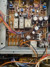
Hello there. Recently got a distressed g7500 back up and running. One of my last checks was to look it over for any potential hot spots or any more shorted parts with my ir camera.

I have noticed that r602 in particular gets quite hot and was wondering if this should be a major concern or is pointing to another problem. R601 and R604 are also running quite warm but seem to be in a safer range. The unit was playing for quite some time with the cover off. I dont see any discoloration or notice anything else but just figured i should ask.

20261002_104541.jpg20261002_104549.jpg20261002_104601.jpg20261002_104708.jpg20261002_104639.jpg
 
Register to hide this ad
I'd want to check actual power dissipation but anything below about 180 F should be OK for a resistor. Some might say even hotter. Also be careful with IR readings as you don't know the emissivity of the part. That can alter the reading by a huge amount. Things I really want to know, I paint flat black! Probably not what you want to do here. Double check with thermocouple.
 
I'd want to check actual power dissipation but anything below about 180 F should be OK for a resistor. Some might say even hotter. Also be careful with IR readings as you don't know the emissivity of the part. That can alter the reading by a huge amount. Things I really want to know, I paint flat black! Probably not what you want to do here. Double check with thermocouple.
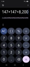
I have a temp probe for cooking but not sure how accurate the reading is. Also not sure if im calculating the power going through the resistor correctly. Im showing 147vdc across the resistor. 147²÷8200 ohm shows 2.6w where this is spec'd as a 2w resistor.

Screenshot_20261002_114002_Calculator.jpg20261002_113810.jpg20261002_113800.jpg
 
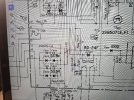
Looks like its purpose is as a 'bleed resistor' for the main filter capacitors. According to the schematic it's expecting to see 126V (63V+63V) which might mean that your input voltage adjustment is set incorrectly, or you have higher than average mains voltage at your location.

If you are concerned about power dissipation, you could easily increase the resistance to say 10KΩ or 12KΩ for a useful reduction in power dissipation. (to 2.16W or 1.8W).
 
Looks like its purpose is as a 'bleed resistor' for the main filter capacitors. According to the schematic it's expecting to see 126V (63V+63V) which might mean that your input voltage adjustment is set incorrectly, or you have higher than average mains voltage at your location.

If you are concerned about power dissipation, you could easily increase the resistance to say 10KΩ or 12KΩ for a useful reduction in power dissipation. (to 2.16W or 1.8W).
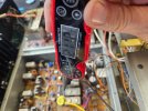
Ahhhhh you got it. Just spotted this after you pointed out the higher than normal voltages. Unit was set to 100v!

Just switched it to 120v

Resistor is showing 120v drop which should be about 1.75w

20261002_120643.jpg20261002_120720.jpg
 
Last edited:
Back
Top Bottom