• The move to the new server is done. There are some software and database maintenance updates in process. This has us passing the hat around to help out. We appreciate any donations. Seriously, even a dollar helps. The payment page may be found here - https://www.audiokarma.org/support.html

G-9700 F-3074 Driver Board Repair

lambord

Active Member
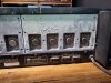
I purchased a non-working g-9700. The seller said he sent 1 of the driver boards to a "professional" to have it repaired and when he got it back it still did not work.

I do not have much experience repair these but I got it at a fair price to if I can not repair it then I can part it out.

*Any test I'm doing so far is using a dim bulb tester*

If I remove both driver boards the unit powers on and relay clicks on
If I put in 1 of either board the unit will stay in protection mode with the flashing protection light
The original board has a resistor that starts to smoke (r20) when unit is turned on. The "repaired" board has nothing smoking but wont come out of protection mode.

My question is if I only have one channel driver board in the unit that is working properly, should it be able to come out of protection mode?

Trying to determine if I have at least 1 functioning driver board
 
Register to hide this ad
Put the boards aside for a minute and check the output transistors. That's often where the trouble starts.

- Pete
 
Put the boards aside for a minute and check the output transistors. That's often where the trouble starts.

- Pete

Im no expert but I removed all 8 and they all seem to be testing correctly after googling a bit on how to test them. All also look to be original and not replaced. But the thermal compound is a little messy, not sure if that looks factory to you or if someone has been in here already
20230404_192335.jpg 20230404_192339.jpg
 
The chart is what I am testing transistors with, let me know if this is incorrect please.
upload_2023-4-5_11-33-32.png

Results below are all the problem transistors I found

* Repaired Board *
tr05 (SA/PNP) - Collector to base diode drop (+ on base, - on collector has value .487)
tr06 (SC/NPN) - Base to emitter diode drop (- on base, + on emitter .486)
tr08 (SA/PNP) - Base to emitter open circuit (- on base, + on emitter OL)
tr09 (SC/NPN) - Base to emitter diode drop (- on base, + on emitter .280) and collector to base diode drop
tr10 (SA/PNP) - Emitter to base diode drop (+ on base, - on emitter has value .278)

* Original Board *
tr04 missing. I purchased KSA1381ESTU transistors from Mouser for a replacement of tr04 but have not installed it yet because I am not confident it is a like for like replacement
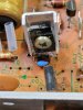
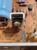
tr05 (SA/PNP) - Emitter to base diode drop (+ on base, - on emitter is reading .483v). Also comparing the two board this transistor is in different holes than repaired board. The original board labels are off from where transistor actually is, maybe repairman was just following the board labels?

20230405_112915.jpg 20230405_112859.jpg

tr06 (SC/NPN) - Base to emitter diode drop (- on base, + on emitter reading .483v)
tr09 (SC/NPN) - Base to emitter diode drop (- on base, + on emitter reading .280v)
tr10 (SA/PNP) - Emitter to base and collector to base diode drop
 

Attachments

  • upload_2023-4-5_11-17-5.png
    upload_2023-4-5_11-17-5.png
    19 KB · Views: 16
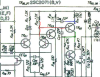
Don't trust the markings on the board. Look at the schematic and determine what each leg of the transistor connects to. Then determine the positions of those terminals on the transistor you are using and match them up. You need to remove the transistor from the circuit to check it with an ohmmeter.

- Pete
 
Don't trust the markings on the board. Look at the schematic and determine what each leg of the transistor connects to. Then determine the positions of those terminals on the transistor you are using and match them up. You need to remove the transistor from the circuit to check it with an ohmmeter.

- Pete

I think the board markings are incorrect like you were saying. Repaired board had it in the wrong spot. I will remove and test transistors

upload_2023-4-7_12-11-33.png upload_2023-4-7_12-12-2.png
Thanks
 

Attachments

  • upload_2023-4-7_11-51-9.png
    upload_2023-4-7_11-51-9.png
    266.9 KB · Views: 9
  • upload_2023-4-7_12-0-29.png
    upload_2023-4-7_12-0-29.png
    410.2 KB · Views: 9
  • upload_2023-4-7_12-1-23.png
    upload_2023-4-7_12-1-23.png
    204.4 KB · Views: 9
Back
Top Bottom